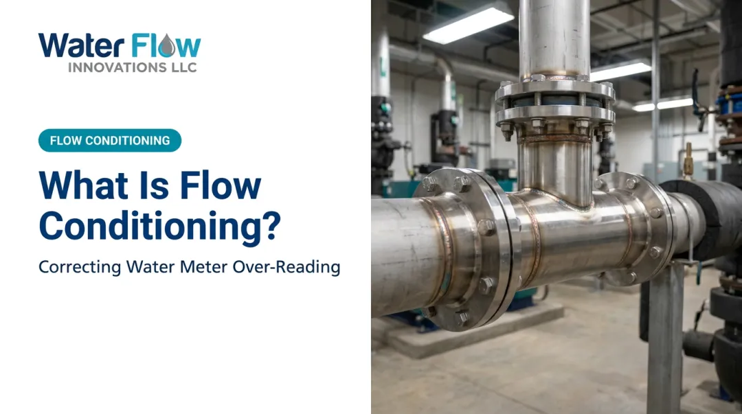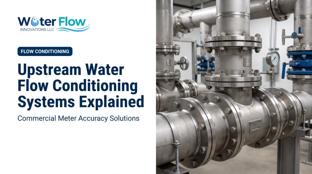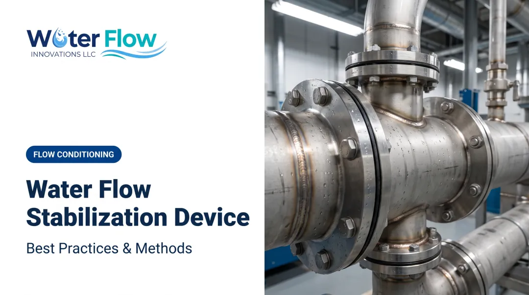

A 2021 peer-reviewed study confirmed that an upstream elbow alone can distort centrifugal-pump suction flow enough to trigger cavitation-pressure disturbances, and separate cavitation research links that distortion to pressure pulsation and vibration (ScienceDirect, 2021). That's where an upstream hydraulic conditioner comes in: a device installed to serve the pump or meter, straightening out flow before it causes damage.
This guide covers how these conditioners work, why placement matters so much, and how proper conditioning protects equipment while cutting costs.
Key Takeaways
- Bends, valves, and reducers distort velocity profiles, causing cavitation, vibration, and premature pump wear
- Flow conditioners restore symmetric, stable flow for the pump or meter
- Proper conditioning reduces energy waste, extends equipment life, and corrects meter over-reading
- Conditioner type: tube bundle, perforated plate, tab-type, or specialized device must match your pipe layout and constraints
What Causes Flow Disturbances Upstream of Pumps
Every elbow, tee, valve, and diameter change in a pipe run disrupts the water moving through it. These fittings generate swirl, turbulence, and asymmetric velocity profiles that don't just disappear a few feet downstream.
Industry metering standards like ASME MFC-3M and ISO 5167 call for straight-run lengths between fittings and measurement devices. Fitting-specific requirements vary by device geometry and beta ratio (ASME MFC-3M).
Pumps & Systems recommends a 5D–10D straight run between a pump inlet and any suction-line obstruction, a rule of thumb that's often impossible to hit in real facilities.
That distortion damages equipment in a clear sequence:
- Distorted inlet flow increases pressure pulsation and vibration
- Vibration accelerates bearing wear and shaft misalignment
- In severe cases, distortion contributes to cavitation damage
Common Real-World Constraints
Space is the enemy of textbook straight-run requirements. Many facilities simply can't add 10+ diameters of straight pipe without a major repiping project:
- Retrofits in mechanical rooms never designed for extra equipment
- Offshore or industrial layouts with fixed structural steel
- Legacy piping where a reducer sits inches from the pump flange
This is exactly the scenario upstream conditioners were built to solve.
How Upstream Hydraulic Conditioners Work
Conditioners use internal geometry, vanes, tubes, perforations, or proprietary elements to break up swirl and redistribute velocity symmetrically before flow reaches sensitive equipment.
Common conditioner types:
| Type | Strength | Weakness |
|---|---|---|
| Tube bundle | Removes tangential flow, restores symmetry | Some added turbulence, possible debris retention |
| Perforated/Zanker plate | Strong swirl suppression in compact runs | Higher pressure loss, clogs in dirty service |
| Honeycomb | Effective when placement/thickness is engineered correctly | Fouling risk not well quantified |
| Tab-type | Lower loss, tolerates dirtier flow, fits inside elbows | Pump-specific performance data is limited |

A 2023 CFD study found that a 19-tube bundle placed after a double bend removed tangential velocity and helical flow structures, pushing the profile back toward a straight-pipe pattern (Taylor & Francis, 2023). Making the tubes longer produced only marginal extra benefit past a certain point.
Every conditioner design has to balance conditioning effectiveness against pressure loss. A device that eliminates 100% of swirl but adds significant head loss can hurt pump NPSH and energy costs elsewhere.
That tradeoff is why multi-function designs matter upstream of a pump. Water Flow Innovation's Flow Conditioning Device (FCD) combines four elements in one unit:
- Air/gas removal
- Pressure regulation
- Check valve (reverse-flow prevention)
- Turbulence elimination
The air separation stage creates static back-pressure that drives bubbles out of the flow path and leaves a more homogeneous water column. With pressure regulation and reverse-flow prevention in the same package, the FCD is built for negligible pressure loss while steadying the velocity profile the pump inlet actually sees.

Why Upstream Placement Is Critical for Pump Performance
Where you install a conditioner matters almost as much as which type you choose. Installing it immediately upstream of the pump inlet ensures flow entering the impeller is already stabilized, preventing uneven loading and reducing cavitation risk.
The Hydraulic Institute's guidance backs this up directly: maximize straight pipe immediately before the suction nozzle and avoid close short-radius elbows wherever possible (Pumps & Systems, 2023).
Upstream placement delivers three practical gains:
- Stabilizes flow before it reaches the impeller
- Reduces cavitation risk and uneven mechanical loading
- Protects downstream instrumentation from residual swirl
Swirl throws off flow meter readings. Those measurement errors feed into billing and process control, so conditioning at the inlet protects both the pump and the data you run on.
A 2006 power-plant retrofit shows the same idea under tight geometry. Two boiler-feed pumps received flow through a 90-degree turn immediately followed by a 16-to-14-inch reduction, leaving zero room for a straight run. Engineers installed a tab-type conditioner directly inside the elbow at the pump inlet, redistributing flow without any repiping (Control Engineering, 2006).

Benefits of Proper Hydraulic Conditioning
Stabilizing inlet flow pays off in ways that show up on both the maintenance log and the utility bill.
Mechanical benefits:
- Reduced vibration and cavitation-related noise
- Lower bearing and seal wear over time
- Fewer unplanned shutdowns tied to pump distress
Measurement and billing benefits:
- Improved accuracy at downstream meters
- Correction of billing discrepancies caused by turbulent or aerated flow
For facilities using a certified device like the FCD, the outcomes are documented rather than theoretical. Customers typically see an average 5-30% reduction in combined water and sewer bills, with a documented high of 46%.
Because the FCD installs after the meter with negligible pressure loss, savings show up on the next billing cycle with zero operational disruption. About 90% of customers reach full ROI within 12 months.

Those bill reductions also serve as sustainability evidence. Before-and-after utility bills provide auditable documentation for ESG reporting, LEED credits, and water-intensity tracking—without separate measurement infrastructure.
Selecting and Installing the Right Conditioner
Choosing a conditioner depends on your system conditions and duty—not a generic catalog pick. Key variables to evaluate include:
- Fluid characteristics – viscosity and flow regime affect device behavior and pressure loss
- Solids content – perforated plates and Zanker-style devices clog faster in dirty service
- Tolerable pressure loss – must factor into pump NPSH and energy calculations
- Pipe size and geometry – match to actual internal diameter and available axial length, not nominal size
- Meter type – conditioners qualified for meters aren't automatically validated for pump duty, and vice versa
Once those variables are set, downtime planning and commercial terms determine how fast you can deploy.
Installation timelines matter for planning downtime. For solutions like the FCD, installation is typically completed in about an hour, regardless of pipe size (NPS ½" to 12") or meter type. The device is custom-fabricated to the facility's exact flange and bolt specifications in advance.
Acquisition flexibility also reduces adoption risk:
- Buy or lease – financing options help facilities preserve capital
- 6-month money-back guarantee – no-questions-asked refund window on the purchase price
- Lifetime transferable warranty – stays with the device through ownership or management changes
Frequently Asked Questions
Is there an additive for hydraulic fluid?
Yes. Anti-wear agents, anti-foam compounds, and rust/oxidation inhibitors are common hydraulic fluid additives. They treat fluid chemistry, not the upstream flow disturbances that conditioning devices correct in piping.
What happens when hydraulic fluid gets old?
Aged hydraulic fluid oxidizes, loses viscosity stability, and accumulates varnish, sludge, and acid byproducts. This raises wear risk on components and should be tracked through routine fluid-sampling programs.
What fluid is used in hydraulics?
Common hydraulic fluids include mineral oil-based products, water-glycol mixtures, and synthetic lubricants. Selection depends on operating temperature, pressure, and system compatibility requirements.
How often should upstream straight pipe runs be inspected for flow conditioning needs?
Inspect during any retrofit, capacity expansion, or equipment addition. Unexplained pump wear or meter inaccuracies are also strong signals it's time to review upstream piping geometry.
Can a flow conditioner reduce my water utility bill?
Yes. Certified devices like the FCD correct meter over-reading from turbulent or aerated flow, so billed use drops without changing actual consumption. Water Flow Innovation installations typically save 5–30%, often on the next billing cycle, with a highest documented result of 46%.
What does fitting an upstream conditioner involve on site?
A licensed plumber or mechanical contractor installs a custom-built unit at the municipal supply connection in about an hour, with a brief water shutoff at the meter connection. Upstream piping geometry stays exactly as it is.
What cover applies to the installed device?
A 6-month money-back guarantee on the purchase price, with installation cost non-refundable, so it can be returned if metered consumption does not measurably fall. A lifetime transferable warranty against manufacturing defects also applies, transferring with the property on sale.