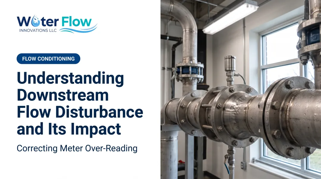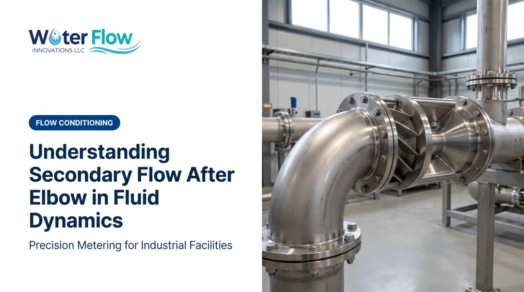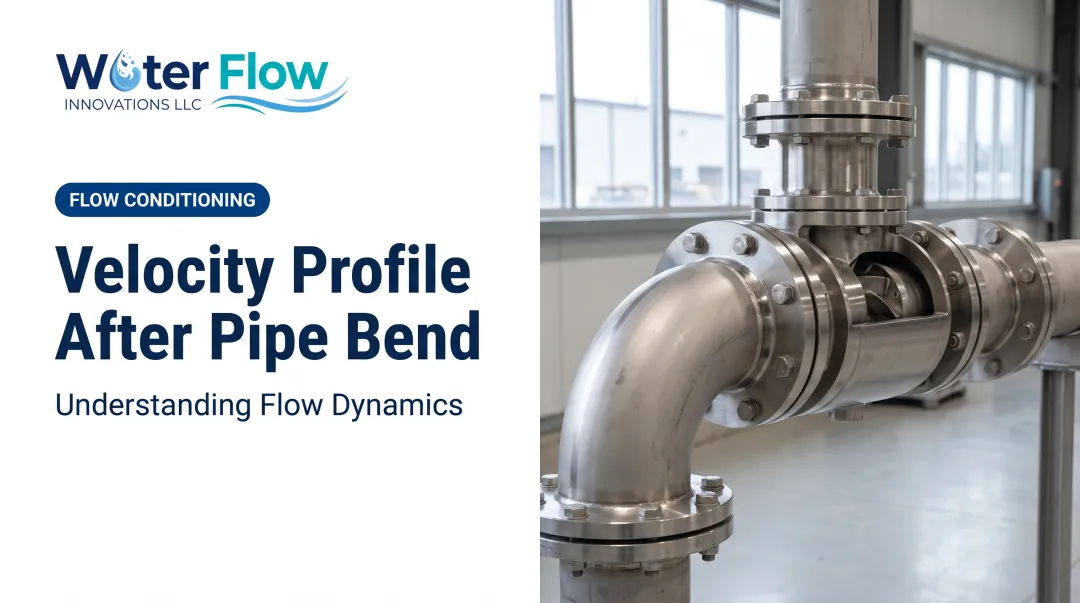

Unresolved flow disturbance isn't just an academic curiosity. It skews pressure drop calculations, throws off instrument accuracy, and — critically — can distort water meter readings enough to inflate a utility bill for months before anyone notices. This article breaks down what causes tee-induced disturbance, how far it travels, why it matters for measurement and system performance, and how to fix it.
Key Takeaways
- Tee junctions generate turbulence and swirl that can persist 10-50+ pipe diameters downstream
- Disturbed flow is a leading, underappreciated cause of water meter over-registration and inflated utility bills
- Straight-run allowances work but aren't always practical; certified flow conditioning devices offer a retrofit-friendly fix
What Causes Flow Disturbance After a Pipe Tee
At a tee, flow either splits (dividing) or merges (combining). Either way, the fluid streams don't blend smoothly. Shear layers form between the fast-moving core and slower fluid near the walls, creating secondary flows and an asymmetric velocity profile as the streams separate or recombine.
Two geometric factors drive the intensity of this turbulence:
- Branch-to-header area ratio: how large the branch pipe is relative to the main run
- Flow split ratio (Qbranch/Qcombined): how much of the total flow diverts into the branch
Engineering references like Miller's Internal Flow Systems and Idelchik's Handbook of Hydraulic Resistance tabulate separate loss coefficients for branching versus combining tees. Both note that these coefficients can even go negative under certain flow distributions: a sign of pressure redistribution between branches, not reduced turbulence overall.
NIST's 2022 review of pipe fitting pressure losses found that tee loss coefficients are more sensitive to flow distribution than to velocity or pipe diameter.
Sharp vs. Rounded Geometry
Sharp 90-degree tee corners promote flow separation, similar to a sharp elbow. Rounded or angled junctions reduce that separation and generally produce lower resistance, but the coefficient still depends heavily on area and flow ratios, so no single number applies universally.
Compounding Effects in Series
Header/branch manifold systems with multiple tees in a row can compound disturbance. This sometimes produces counterintuitive results, such as higher flow rates in a downstream branch than in a branch located closer to the source.

How Far Downstream Does Flow Disturbance Travel
"Development length" refers to the straight pipe distance a fluid needs to return to a fully developed, symmetric velocity profile. For tee-induced disturbance, this is rarely a fixed number.
What the standards actually say:
- API MPMS Chapter 5.3 recommends 20 diameters upstream and 5 diameters downstream for turbine meters near a simple elbow or tee (experience-based, not universal)
- ISO 5167-4 requires spacing rules for multiple upstream fittings, adding measurement uncertainty when minimum spacing is used
- No single standard gives one blanket "tee number" that applies across every meter type
Turbulent (high Reynolds number) flows generally re-develop faster than laminar flows in terms of axial velocity. Swirl components often persist far longer than the velocity distortion itself, though. Swirl alone can skew a downstream reading even after the profile looks visually "normal."
Why Flow Disturbance Matters: Impact on Measurement and System Performance
Install a flow meter, water meter, or pressure sensor too close to a tee without adequate straight-run or conditioning. It will read a distorted, non-uniform velocity profile instead of true flow.
That distortion shows up in bills, energy use, and control loops:
- Water meters over-register or under-register actual consumption, directly hitting utility bills
- PNNL Water Metering Best Practices call for at least 5 diameters upstream and downstream when fittings sit near compound or turbine meters
- Tee-driven turbulence drives meter over-reading in commercial and industrial facilities, along with air entrainment and turbulence from valves, elbows, and pumps
- Unaddressed turbulence increases pressure drop and energy loss across the system
- In process control loops, disturbed flow causes valve hunting and unstable control as feedback signals become inconsistent
Whether the meter over- or under-registers depends on flow split, tee geometry, meter technology, and sensor placement. There's no single universal rule, which is why so many facilities never trace billing anomalies back to a tee three feet upstream of the meter.

Correcting Flow Disturbance: Straight Runs vs. Flow Conditioning
The traditional fix is straightforward on paper: add enough straight pipe upstream and downstream of the tee and the instrument. In practice, this is often impossible.
Common obstacles:
- Retrofit facilities rarely have 20+ diameters of open, straight pipe run available
- Mechanical rooms are space-constrained by design
- Rerouting piping to add straight-run length means downtime, permitting, and cost
When straight-run length is not available, engineered flow conditioners are the practical alternative. Instead of waiting for pipe length to smooth the profile, a conditioner mechanically restores a uniform velocity distribution in a much shorter distance.
Where an FCD Fits
Water Flow Innovation's Flow Conditioning Device (FCD) corrects the turbulence and air entrainment that drive meter over-reading from fittings like tees, elbows, and valves. It is certified to IAPMO, NSF, ANSI, CAN 61, KIWA, GMP, and SQF standards.
Each unit is custom-fabricated in 316L stainless steel (titanium and specialty alloys available) for pipe sizes from 1/2 inch to 12 inches standard, with custom builds up to 36 inches for larger industrial or municipal systems.
The device installs immediately after the water meter using a four-component passive system:
- Air and gas separation — removes bubbles that inflate readings
- Pressure regulation — reduces water hammer and surge from cycling demand
- Check valve (select models) — prevents reverse flow
- Turbulence elimination — slows velocity enough to stabilize the flow and prevent vortex patterns

The FCD is built for negligible pressure loss, so you avoid the larger energy and metering penalty of leaving turbulent, disturbed flow uncorrected.
Best Practices for Managing Tee-Induced Flow Disturbance
A few practical habits help you catch disturbance before it costs money:
- Follow minimum straight-run guidelines from the meter or instrument manufacturer when placing sensors downstream of a tee
- Run a flow audit if you're seeing unexplained billing spikes or inconsistent readings in a piping layout with multiple tees
- Document tee configurations during design (angle, area ratio, flow direction) so disturbance risk is flagged before installation, not after the first suspicious bill
Facilities that skip that last step often discover a tee problem only after months of inflated water and sewer charges. A bill review is then the fastest way to confirm what is actually happening.
Frequently Asked Questions
What is friction loss in a pipe?
Friction loss is the pressure drop from fluid viscosity dragging against the pipe wall as flow moves through the line. The Darcy-Weisbach equation describes it. It differs from the local, fitting-specific losses a tee creates, though both add to total system pressure drop.
How long does it take for flow to stabilize after a tee?
Flow generally needs 10 to 50 pipe diameters of straight run to fully redevelop, depending on Reynolds number, tee geometry, and how severe the initial disturbance is. Swirl often takes longer to dissipate than axial velocity distortion.
Can a tee fitting cause my water meter to read inaccurately?
Yes. Turbulence and asymmetric flow exiting a tee create a non-uniform velocity profile at the meter, which can cause over- or under-registration. This is a commonly overlooked contributor to inflated utility bills.
Do all tees create the same amount of flow disturbance?
No. Branch angle, area ratio, and flow split ratio all affect how much turbulence a given tee generates. A rounded, angled junction typically produces less separation than a sharp 90-degree tee.
What's the difference between a tee and a wye fitting in terms of flow?
A wye introduces or removes flow at an oblique angle, which is gentler than a tee's abrupt right-angle junction. Angled wye junctions typically carry lower loss coefficients, though exact values still depend on geometry.
How can I fix flow disturbance without redesigning my whole piping system?
Certified flow conditioning devices restore a usable flow profile in far less length than natural straight pipe. That makes them a practical retrofit when rerouting pipe for extra straight run would cost too much or disrupt operations.
How much downtime does that retrofit actually involve?
About an hour, with a brief water shutoff at the meter connection. A licensed plumber or mechanical contractor fits the custom-built unit at the supply connection, so no tee, branch, or downstream equipment has to be moved or shut down.
Which facilities most often have meters sited near tees?
Sites with branched distribution off one service: hotels and hospitality, healthcare facilities, multifamily and apartment buildings, commercial office buildings, schools and universities, shopping malls, and food and beverage plants.