
Facility piping routes commonly require elbows, tees, and valves to navigate real-world layouts. Standards bodies like ASHRAE and ASME dedicate entire chapters to designing around these fittings, which tells you something: bends and disturbances aren't the exception, they're the norm.
While primary flow (the bulk forward movement of fluid) is well understood, its rotational cousin often gets ignored. That oversight leads to inaccurate metering, energy losses, and system inefficiencies that get blamed on the wrong culprit. This guide breaks down the actual mechanisms behind secondary flow and what it does to your system in practice.
Key Takeaways
- Secondary flow is a weaker rotational pattern layered on primary axial flow at bends, fittings, and junctions
- Centrifugal forces and boundary-layer imbalance drive these cross-stream motions
- Unmanaged secondary flow causes pressure loss, erosion, uneven profiles, and skewed meter readings
- Risk peaks downstream of bends, near meters, and anywhere precise measurement matters
- Flow conditioning straightens distorted profiles and corrects the resulting measurement errors
What Is Secondary Flow in Pipes?
Secondary flow is the rotational or swirling motion superimposed on the primary axial flow direction. It's typically induced by pipe curvature, fittings, or geometric asymmetries.
Bends and fittings force a pressure gradient across the pipe's cross-section. The slower-moving boundary layer near the pipe wall can't balance that gradient the way faster core fluid can. The mismatch produces cross-stream circulation — fluid literally curling sideways as it moves forward.
Secondary flow is not turbulence. Turbulence is random fluctuation; secondary flow is a structured, rotational pattern. They interact, but they're distinct phenomena with different causes.
Even modern piping designs can't eliminate bends, fittings, or valves entirely. That means secondary flow persists in nearly every real-world system, not just older or poorly designed ones.
The Two Classical Types
Fluid dynamics researchers split secondary flow into two categories:
- First kind (Prandtl): Curvature and pressure-driven, seen in bends and elbows. Can occur in laminar or turbulent flow.
- Second kind: Turbulence-driven, generated by anisotropic stresses in non-circular ducts like square or rectangular channels.
The distinction matters for diagnosis. A downstream elbow problem and a fully developed square-duct problem require different fixes, even though both display swirling secondary motion.
How Does Secondary Flow Develop?
Secondary flow follows a predictable sequence: disturbance, growth, and eventual decay downstream.
Initiation
Secondary flow kicks in whenever fully developed flow hits a bend, elbow, tee, valve, or diameter change. Geometry and fluid inertia cause it; operators don't.
Double bends or closely spaced fittings compound the problem. Flow simply doesn't have enough distance to re-stabilize between disturbances, so the effects stack.
Centrifugal Force and Vortex Pairs
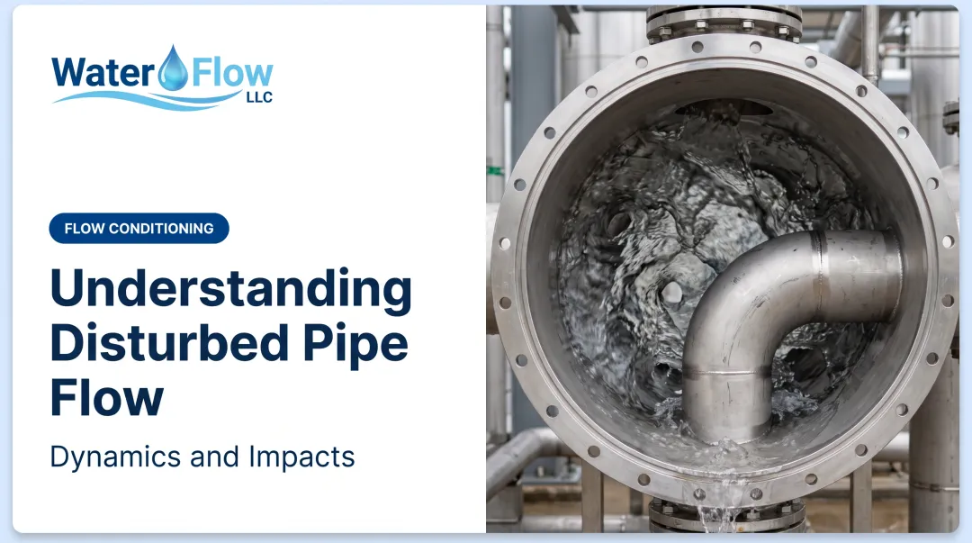
At a bend, centrifugal force pushes faster-moving fluid in the pipe's core outward, while slower near-wall fluid gets pulled inward. This creates a pair of counter-rotating vortices.
The result is a distorted cross-sectional velocity profile — often a skewed "camel's-back" shape instead of the smooth, symmetric profile of straight pipe. Tighter curvature and lower fluid viscosity intensify the effect; Reynolds number and bend geometry set how strong it gets.

Regulation and Decay
Flow doesn't snap back to normal the instant it clears a bend. It needs a straight run to redevelop, and how long that run needs to be is highly configuration-specific.
Published guidance varies considerably:
| Source | Straight-run figure | Context |
|---|---|---|
| Georgia EPD ultrasonic meter guidance | ~10D upstream, 5D downstream | Technology-specific, not universal |
| ISO/OIML water meter testing | 15D upstream, 5D downstream | Specified test condition |
| Double-elbow experiments | Up to 89D to reduce swirl below 2° | Severe-case research finding |

That last figure is worth sitting with. Severe double-elbow configurations have measured swirl persisting for dozens of diameters, far beyond what most facility layouts allow. There's no single universal rule. The right straight-run length depends on pipe diameter, Reynolds number, and the exact fitting sequence involved.
This matters because any measurement or process step happening before full redevelopment is working with a distorted profile, not the true flow.
Downstream Consequences
Flow does redevelop downstream, but only after it loses pressure head and redistributes momentum. Flow meters, control valves, and pumps installed too close to a bend read the disturbed profile instead of the actual flow rate.
This is directly tied to a well-documented real-world problem: distorted velocity profiles are a recognized contributor to water meter over-registration in commercial and industrial facilities.
Effects of Secondary Flow on Pipe Systems
Secondary flow does more than rearrange streamlines. It steals energy from the main flow, distorts what meters see, and concentrates stress on pipe walls and fittings.
Pressure Head Loss
The most immediate hydraulic cost is pressure head loss. Energy that should push fluid downstream is partly diverted into cross-stream rotation. At elbows, research ties that loss to wall friction, secondary circulation, and flow separation together, not secondary flow alone.
Meter Accuracy and Over-Reading
Non-uniform velocity and swirl skew readings on differential-pressure, turbine, and ultrasonic meters:
- One ultrasonic meter study reported maximum errors mainly in the 2%–4% range across common disturbances
- A NIST program found most tested-meter errors between 0%–3%, with one worst case at -14%
- Turbine meters showed positive or negative meter-factor shifts depending on swirl direction

These figures are not universal billing factors. They do show a consistent pattern: meters calibrated for fully developed flow misreport when the profile is distorted. In commercial water service, that often means over-reading and higher water and sewer charges without any real increase in use.
Physical Wear and Product Quality
Secondary-flow vortices also drive long-term system effects:
- Erosion and solids deposition along walls and fittings, much like sediment build-up on the inside of a river bend; slurry-pipe work links particle migration toward bend walls with faster wall loss
- Uneven mixing in food, beverage, and pharmaceutical lines when spiral currents are ignored in layout and sizing
Addressing Distorted Flow
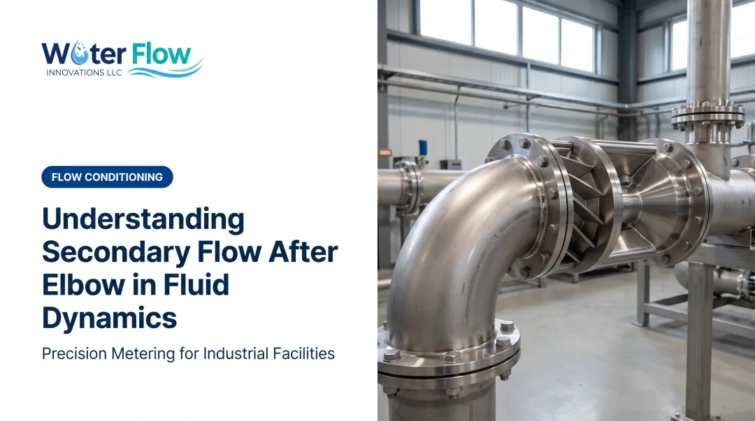
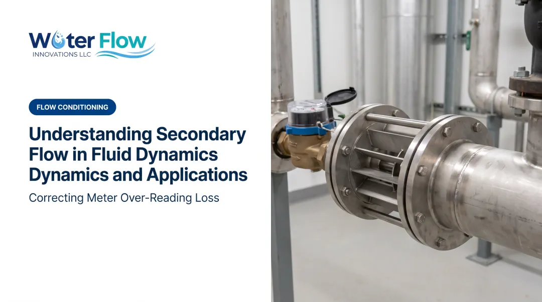
Flow conditioning limits how much of that distortion reaches the meter. Water Flow Innovation's Flow Conditioning Device (FCD) is a certified unit built around four functions in one body: air and gas separation, pressure regulation, reverse-flow check, and turbulence elimination. Together they present a more stable, homogeneous column to the meter so readings track actual consumption more closely, with negligible pressure loss in normal operation.

Where Secondary Flow Is Most Critical
Secondary flow effects peak immediately downstream of bends, double bends, tees, and control valves. These conditions show up constantly in HVAC loops, process piping, and metering stations.
High-risk environments share a few traits:
- Tight-radius bends combined with high velocity (higher Dean number, meaning stronger curvature-driven vortices)
- Non-Newtonian fluids such as industrial slurries or viscous food products, where rheology reshapes vortex structure and particle transport
- Closely spaced fittings with no room for the profile to redevelop
Different industries hit the same risk in different places:
- Hydronic HVAC: circulator pumps and zone valves
- Industrial manufacturing: process meters and CIP cycles
- Municipal water: metering stations downstream of directional changes in the main
The shared outcome across all three is flow-measurement inaccuracy near meters and sensors. Flow conditioning devices such as Water Flow Innovation’s FCD (NPS 1/2"–12", 316L stainless) are built to straighten that disturbed profile at the meter, covering the pipe sizes common in these commercial and industrial systems.
Conclusion
Secondary flow is a physically unavoidable consequence of pipe geometry. Anywhere fluid changes direction, some of that motion becomes rotational instead of forward.
Understanding these mechanisms leads to better decisions: proper meter placement, adequate straight-pipe runs where space allows, and certified flow conditioning where it doesn't.
Water Flow Innovation's FCD corrects meter over-reading and reduces utility costs without disrupting facility operations. Installation typically takes about an hour, and savings appear on the next billing cycle.
Frequently Asked Questions
What is primary and secondary flow?
Primary flow is the main, bulk movement of fluid along the pipe's axis. Secondary flow is a weaker, rotational or swirling motion superimposed on it, usually caused by bends or fittings.
How much flow can go through a 2-inch pipe?
For NPS 2 Schedule 40 pipe (2.067" actual ID), expect roughly 21 GPM at 2 ft/s to 84 GPM at 8 ft/s. Pressure, roughness, and length set true capacity, and secondary flow near fittings can skew meter readings of that flow.
What are three types of flow?
The three types are laminar (Re < 2,300), transitional (2,300–4,000), and turbulent (Re > 4,000). Secondary flow can appear with any of them, and it is most pronounced in turbulent conditions.
Does secondary flow waste energy or water?
Secondary flow itself doesn't waste water. But the pressure losses and meter inaccuracies it causes can inflate utility bills without any real change in actual consumption.
How far downstream of a bend should a flow meter be installed?
Most guidance calls for 10 to 30 pipe diameters, depending on fitting type and meter technology. Severe double-bend layouts can need more distance, so always check the meter manufacturer's installation table.
Can secondary flow be corrected without changing pipe design?
Yes. Certified flow conditioning devices retrofit at the meter flange and correct distorted profiles without re-engineering the piping. Installation usually takes about one hour of water shut-off time.
What does correcting the swirl actually return on the bill?
Documented installations average a 5–30% reduction in combined water and sewer charges, with a highest documented single result of 46%, appearing on the very next billing cycle.
Does the inflated reading carry into the sewer line as well?
Usually. Sewer is normally derived from metered intake rather than measured discharge, commonly 80–120% of the water charge, so a swirl-driven error is billed on both lines each cycle.