
Straight-pipe-run requirements around valves show up consistently across flow meter manufacturer specifications, ISO standards, and AWWA guidance. That's not a coincidence. It's a documented response to a real problem.
Valves are non-negotiable for system control. But their internal geometry disturbs flow in ways facility managers often don't notice until a water bill looks wrong for no obvious reason. This guide breaks down exactly how that happens, and what you can do about it.
Key Takeaways
- Valves distort flow velocity profiles through throttling, turbulence, and swirl, causing meters to over- or under-read
- Error severity depends on valve type, how far open it is, and its distance from the meter
- Turbine, DP, and ultrasonic meters react more to valve disturbance than magnetic or Coriolis meters
- Flow conditioning restores accuracy when you lack the straight-pipe run the meter needs
- Uncorrected, valve-induced errors translate directly into inflated water and sewer bills
What Is a Valve's Role in a Flow System?
A valve is a mechanical device that starts, stops, throttles, or diverts fluid flow within a pipeline. Pipes alone can't do this. Systems need process control, safety isolation, and pressure regulation, and valves are how facilities get it.
A valve is not a flow measurement device, even though manufacturers rate valves using flow coefficients like Cv or Kv.
Emerson's Control Valve Handbook defines Cv as the flow capacity in gallons per minute of 60°F water at a 1 psi pressure drop. That figure is a sizing metric, not an accuracy indicator.
Common valve types used for flow regulation include:
- Gate valves — designed for fully open or fully closed service, not throttling
- Globe valves — built for frequent operation and throttling duty
- Ball valves — quick-operating, often used in control applications
- Butterfly valves — compact, common in larger pipe diameters
- Control/throttling valves — engineered specifically for variable positioning
Each type creates a distinct disturbance signature downstream. Valves stay indispensable for control; the work is managing those disturbances, not removing the valves.
How Do Valves Affect Flow Measurement Accuracy?
Most flow meters are calibrated against a fully developed, symmetrical velocity profile. Valves interrupt that profile through a few specific mechanisms.
Turbulence and Swirl Generation
Fluid accelerates as it passes through a restricted valve opening, then exits with an asymmetric, disturbed velocity profile. A partially open, throttling valve generates far more turbulence than a fully open one of the same type.
This turbulence doesn't disappear a few inches downstream. A 2023 water-loop study on a knife-gate valve tested one-third and one-half closures Piechota et al., 2023. Distortion peaked near 3–4 pipe diameters (D) downstream, and correction factors did not stabilize until 12D or more. Half-closed valves disturbed the profile more than valves closed one-third of the way.
Valve Position and Type-Specific Effects
Different valve types create different disturbance patterns based on their internal geometry. A 2020 study testing ten large water meters against upstream butterfly and gate valves found dramatic swings depending on closure position MDPI, 2020:
- Butterfly valve, 90% closed at 0D: one ultrasonic meter model showed errors as high as 293–768%, depending on flow rate
- Gate valve closures above 50%: produced over-registration exceeding +30%
- Added straight pipe: narrowed error extremes from roughly ±100% at 0D down to +10/−15% at 10D

Turbulence from valve throttling also compounds with air entrainment and pressure fluctuation, which drives meters further into over- or under-reading.
Meter Sensitivity Variations
Not every meter technology reacts the same way:
- Turbine and differential pressure meters infer flow directly from velocity, so they're highly sensitive to profile distortion
- Ultrasonic meters (particularly single-path, transit-time designs) can show significant orientation-dependent error close to a disturbance
- Magnetic meters tend to be more tolerant of profile distortion but are not immune
- Coriolis meters measure via tube dynamics rather than velocity profile, making some models notably resistant to valve-induced turbulence
The operational outcome is the same regardless of technology: inconsistent readings, poor repeatability, and consumption records that don't match actual usage.

Where Valve-Related Measurement Errors Show Up Most
Facilities with retrofits, tight mechanical rooms, or limited straight-pipe space face the highest risk of valve-meter placement conflicts. When a building wasn't designed with meter accuracy in mind, valves and meters often end up crowded together with no room for proper spacing.
High-risk environments include:
- Manufacturing plants with dense pipe runs
- Multifamily and high-rise buildings with compact mechanical rooms
- Hospitals and healthcare facilities with retrofit constraints
- Hotels, universities, and campus buildings with aging infrastructure
In these settings, valve-induced measurement error is frequently the hidden cause behind persistently high water bills that don't correlate with actual usage patterns. Facility managers often assume a leak or usage spike, when the meter is over-reading from turbulence it wasn't designed to handle.
Correcting Valve-Induced Flow Measurement Errors
The industry-standard fix is straightforward in concept: give the meter enough straight, undisturbed pipe upstream and downstream of the valve. Requirements vary significantly by technology and manufacturer, but commonly range from roughly 5 to 30 pipe diameters.
That's rarely simple to achieve. Mechanical rooms are cramped, retrofits inherit old piping layouts, and moving equipment isn't always feasible.
Flow conditioners address that constraint. They eliminate swirl and restore a stable velocity profile without the full straight-run distance a bare pipe would need.
Water Flow Innovation's Flow Conditioning Device (FCD)
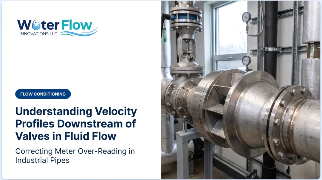
Water Flow Innovation offers a certified Flow Conditioning Device built to correct meter over-reading from turbulence and air entrainment, including disturbance from upstream valves. The FCD uses a four-component system:
- Air/gas removal — creates static back pressure that displaces air, producing a homogeneous water column so the meter isn't registering air as water
- Pressure regulation — reduces water hammer and pressure surges from valve cycling and variable demand
- Check valve — minimizes pressure spikes and prevents reverse flow that can let air re-enter the line
- Turbulence elimination — slows velocity enough at the meter to prevent vortex flow without reducing actual water usage

The FCD is custom-fabricated in 316L stainless steel for pipe sizes from ½ inch through 12 inches and fits any meter type. It carries IAPMO, NSF, ANSI, CAN 61, KIWA, GMP, and SQF certifications. Installation typically takes about an hour.
Its negligible pressure loss design means valve-controlled system performance isn't disrupted while measurement accuracy improves.
In documented installations, correcting over-reading has produced 5–30% average water and sewer bill reductions, with 46% as the highest documented result. Because correction begins immediately, savings typically appear on the next billing cycle.

Conclusion
Valves are essential. They're also unavoidably disruptive to flow measurement accuracy through turbulence, swirl, and profile distortion. That's how fluid mechanics works near a throttled opening.
That reality drives three practical choices:
- Maintain proper valve-meter spacing wherever the layout allows
- Select meter technology with known swirl and profile sensitivities in mind
- Use flow conditioning when space makes textbook spacing impossible
Getting those choices right protects process control and billing accuracy.
Frequently Asked Questions
Does a higher valve Cv mean more flow?
A higher Cv indicates greater flow capacity at a given pressure drop, but it doesn't by itself indicate measurement accuracy. Cv describes the valve's flow characteristic, not the velocity profile it produces downstream.
How does fluid viscosity affect flow rate and flow measurement?
Higher viscosity fluids move slower through valves and piping, which alters the Reynolds number and how quickly the flow profile develops. This affects meter accuracy differently depending on the technology involved.
Which types of valves are used to regulate flow?
Globe, ball, and butterfly valves are among the most common types used to regulate flow. Each has a different internal geometry, so each produces a distinct disturbance pattern downstream.
Does closing a valve increase pressure?
Partially closing a valve increases upstream pressure and restricts downstream flow. It also intensifies turbulence near the throttling point, which can compound measurement error.
How far should a flow meter be installed from a valve?
Requirements vary by meter technology, generally ranging from a few to about 30 pipe diameters. Manufacturer specifications should always take priority over generic rules of thumb.
Can a flow meter be fixed if it's already reading inaccurately due to nearby valves?
Yes. Certified flow conditioning devices installed after the fact can often correct the disturbance without relocating the meter or valve. This is typically far more practical than a full re-pipe.
What is reviewed to confirm valves are the cause?
A free assessment of your water and sewer bills together with meter size, pipe size, line pressure, and PRV configuration. Those inputs establish whether the connection is over-registering and size the correction, with no obligation.
Which facilities typically have valves crowded near the meter?
Sites with compact mechanical rooms and heavy throttling: commercial office buildings, hotels, hospitals, multifamily and apartment buildings, schools and universities, shopping malls, and chemical or food and beverage plants.