
Facilities feel this in ways that rarely get traced back to the source: flow meters that read inconsistently, control loops that hunt and overshoot, unexplained pipe noise, erosion at fittings, and water meters that quietly over-register usage.
This article breaks down what a velocity profile actually is, why valves distort it, how far that distortion travels downstream, and what facilities can do to correct it.
Key Takeaways
- Valves create asymmetric, swirling profiles that can need 20 to 50 pipe diameters of straight run to resolve
- Distorted profiles cause meter errors as high as 3.6% when straight-run distance is insufficient
- Straight pipe, flow straighteners, or purpose-built conditioning devices can restore a usable flow profile
- Turbulence and air entrainment from valves drive water meter over-registration and inflated utility bills
What Does "Downstream of a Valve" Mean?
"Downstream" refers to the section of pipe immediately after a valve, where fluid exits into a zone of changing pressure and velocity conditions. It's the stretch of piping most affected by the turbulence the valve just introduced.
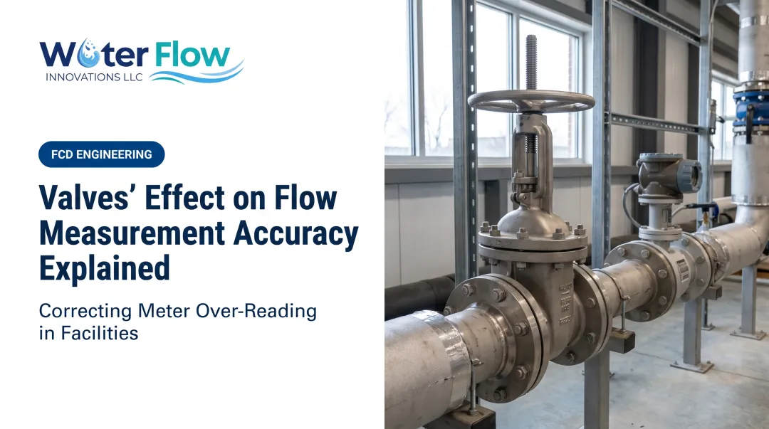
Not all valves disturb flow equally. Globe valves, control valves, ball valves, and butterfly valves each throttle fluid differently, and the geometry of that throttling determines how severe the downstream disturbance becomes.
For example:
- A modulating control valve at partial opening creates a highly disturbed downstream pattern
- A fully open ball valve produces far less disruption in the same pipe run
That difference in disturbance severity is what shapes the velocity profile farther along the line.
What Is a Velocity Profile?
A velocity profile describes how fluid speed varies across a pipe's cross-section, from the centerline out to the wall. The result is a shape across the diameter, not a single average value.
Most flow meter manufacturers calibrate their devices assuming an ideal profile: symmetric, free of swirl, and fully developed. The actual shape depends on:
- Reynolds number — governs whether flow is laminar or turbulent
- Fluid viscosity — higher viscosity thickens the boundary layer and changes the gradient from wall to centerline
- Pipe wall roughness — affects the boundary layer near the wall
Why the "Ideal" Shape Matters
Valves, elbows, tees, and reducers all distort this ideal shape into something asymmetric or swirling. That distortion changes what the meter "sees."
A meter reading a distorted profile doesn't fail in a predictable way. It introduces non-repeatable error: the same actual flow rate can register differently depending on upstream conditions that day. That unpredictability is what makes distorted profiles so difficult to diagnose in the field.
Laminar vs. Turbulent Velocity Profiles
Understanding the baseline shapes helps explain why distortion is such a problem.
- Laminar flow (roughly below Reynolds number 2,300): parabolic profile—centerline fluid moves much faster than fluid near the wall, dominated by viscous forces. This is classic Poiseuille flow, tied to the Hagen-Poiseuille relation (pressure drop, viscosity, length, diameter).
- Turbulent flow: squared-off profile—velocity stays nearly uniform across most of the core, with a thin near-wall boundary layer and a steep gradient.
- Transitional flow: unpredictable mix that shifts between laminar and turbulent behavior; a known source of poor meter repeatability.
Most industrial water and process systems operate in turbulent flow. That squared-off profile is the practical baseline most facilities should understand, since it's what their meters are calibrated against.
How Valves Distort the Velocity Profile
Modulating control valves rank among the most disruptive elements in a piping system, often worse than a single elbow or tee. The severity depends on valve opening and disturbance type.
The Mechanics of Distortion
Throttling through a partially open valve generates:
- Counter-rotating vortices on either side of the flow restriction
- Swirl that persists well beyond the valve body
- Asymmetric velocity distribution across the pipe cross-section
On butterfly valves at restricted openings, narrow high-speed jets and vortices can persist roughly 3 to 6 pipe diameters downstream. Recovery length still varies with opening angle and Reynolds number.
How Far Does It Really Travel?
Manufacturer installation guides make one point clear: there is no single universal recovery distance. Straight-run requirements vary by meter type and disturbance:
| Disturbance Type | Required Upstream Run |
|---|---|
| Pipe reduction | 15DN |
| Single 90° elbow or tee | 20DN |
| Two 90° elbows (3D configuration) | 25DN |
| Control valve | 40DN |
| Two 90° elbows in series | 50DN |
These figures come from vortex meter installation manuals and illustrate the scale of the problem — a control valve can demand twice the straight-run distance of a single elbow.

The Air Entrainment Problem
Beyond swirl, valves also introduce micro-turbulence and air entrainment. When entrained air bubbles pass through the meter, the device records a mixed volume rather than water alone, so it registers more flow than was actually delivered.
For commercial and industrial facilities, that over-registration shows up as inflated water and sewer bills.
Why This Matters for Flow Measurement and Facility Costs
Flow meter technologies — orifice, vortex, ultrasonic, turbine — all assume an ideal, symmetric profile at the point of measurement. Distortion introduces measurable inaccuracy, and manufacturer data backs this up.
Emerson's own documentation shows a traditional orifice meter with only 2 diameters of straight run producing a 3.6% error, compared to a conditioning-plate design rated for 0.5% accuracy under the same constraint.
That's not a rounding error at scale. For a facility with a large water bill, a few percentage points of meter over-registration means:
- Paying for water that was never actually delivered
- Sewer charges calculated on inflated intake volume, since many utilities bill sewer as a percentage of metered water
- Silent month-over-month overcharges until upstream flow conditions are checked
Distorted velocity profiles show up as a recurring line item on the utility bill.

Correcting Distorted Velocity Profiles: Solutions
Traditional Fixes
The conventional approach has always been:
- Add straight pipe runs: 20D to 50D depending on the disturbance, giving turbulence room to naturally dissipate
- Install flow straighteners or vanes: Daniel's turbine meter guidance shows straightening vanes can cut a 20D requirement down to 10D
- Relocate meters upstream of valves: avoiding the disturbance entirely where piping layout allows
Where Traditional Fixes Fall Short
In retrofit situations, none of this is simple. A facility with a meter room built decades ago rarely has 20 to 50 pipe diameters of open, straight pipe available. Mechanical rooms are cramped. Meters sit close to valves, elbows, and tees by necessity, not choice.
A Purpose-Built Alternative
This is the gap Water Flow Innovation's Flow Conditioning Device (FCD) was built to close. Rather than relying on distance to let turbulence dissipate naturally, the FCD corrects flow conditions directly.
It is a custom-fabricated 316L stainless steel unit. Standard catalog sizes run from NPS ½" to 12", with custom units up to 36 inches for larger municipal or industrial lines.
It works through four integrated components:
- Air and gas separation, creating a homogeneous water column back through the meter
- Pressure regulation, reducing surges that generate turbulence
- A check valve (on select systems), preventing reverse flow and pressure spikes
- Turbulence elimination, slowing velocity enough at the meter to prevent vortex formation
The device installs immediately after the meter with negligible pressure loss and typically takes about an hour to put in place, with a brief planned water shutoff. No long straight pipe run is required.
Because it directly addresses the swirl and air entrainment causing meter over-reading, facilities using the FCD have documented 5% to 30% reductions in water and sewer bills, with one recorded case as high as 46%. Savings show up on the very next billing cycle, not months later.

Frequently Asked Questions
What does "downstream of a valve" mean?
Downstream is the stretch of pipe right after a valve, where fluid exits into changing pressure and velocity conditions. How severe the disturbance is depends on valve type and how far open it is.
What does velocity profile mean?
A velocity profile is how fluid speed is distributed across a pipe's cross-section, from the wall to the centerline. Shape matters more than average speed, because meters are calibrated to a specific expected profile.
What is the velocity profile for Poiseuille flow?
Poiseuille flow is fully developed laminar flow in a circular pipe. It produces a parabolic profile: centerline speed is highest, and velocity drops smoothly to zero at the wall.
What is the velocity profile like in a pipe with turbulent flow?
Turbulent flow produces a flattened, "squared-up" profile. Velocity stays nearly uniform across most of the pipe, with a thin boundary layer of steep gradient right at the wall.
How far downstream does a valve affect the velocity profile?
Manufacturer guidance ranges from 20 to 50 pipe diameters depending on meter type and valve configuration. Control valves often need around 40 diameters of straight run; there is no single universal number.
Can a distorted velocity profile actually increase my water bill?
Yes. Turbulence and air entrainment from valves can cause meters to register more volume than actually delivered. Flow conditioning devices correct this at the meter, reducing over-registration and lowering bills starting the next cycle.
Why does valve-induced error appear twice on the invoice?
Sewer is generally billed as a share of metered intake rather than measured discharge, commonly 80–120% of the water charge. Volume registered in error therefore carries a matching sewer charge for water that never reached a drain.
How much operational interruption does the fix require?
About an hour, with a brief water shutoff at the meter connection, carried out by a licensed plumber or mechanical contractor at the supply connection. Valves, control loops, and downstream equipment are left in place.