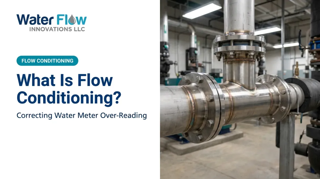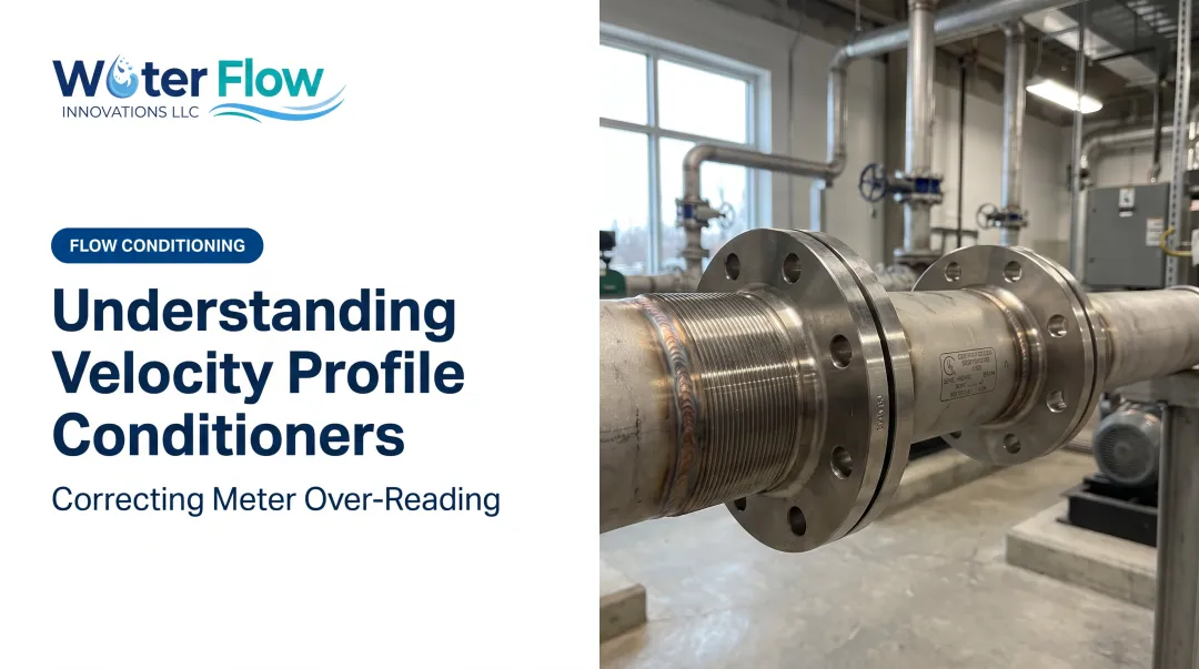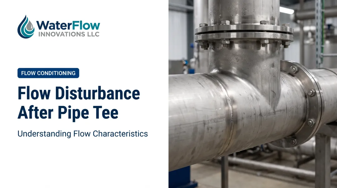

This article breaks down what velocity profiles actually are, how bends distort them, and why that distortion matters for accurate water metering and utility costs. Facility managers, engineers, and plant operators across industrial and commercial water systems deal with this issue daily, often without realizing it's the root cause of inflated bills.
Key Takeaways
- Velocity profiles map fluid speed across a pipe cross-section; bends distort that pattern significantly
- Distorted profiles create asymmetric flow and secondary currents that can persist for many pipe diameters downstream
- Straight-run requirements (often 10-30x pipe diameter) exist to let flow re-stabilize before metering
- Water meter over-registration from distorted flow is a documented cause of inflated utility bills
- Flow conditioning technology corrects these disturbances without disrupting system performance
What Is a Velocity Profile in Pipe Flow?
A velocity profile is the distribution of fluid speed across a pipe's cross-section. Water touching the pipe wall doesn't move (the no-slip condition), while water at the center moves fastest. The shape connecting those two extremes is your velocity profile.
There are two basic shapes to know:
- Parabolic (laminar flow): A smooth curve where centerline velocity is exactly twice the average velocity, described by the Hagen-Poiseuille equation
- Flat/blunt (turbulent flow): A comparatively uniform core velocity with a thin, fast-changing layer near the wall
Reynolds Number Decides the Shape
The Reynolds number tells you which profile you're dealing with. Below 2,000, flow is laminar and parabolic. Above 4,000, it's turbulent with that flatter profile. Between those numbers sits a transitional zone that's neither fully stable nor predictable, according to a 2024 peer-reviewed review of Reynolds number classifications.
In most commercial and industrial piping, turbulent flow is the norm. Typical velocities and pipe diameters push Reynolds numbers well past 4,000. In a factory, hospital, or hotel plumbing system, the velocity profile is almost always the turbulent, blunt shape—not the tidy parabola from a textbook diagram.
How Pipe Bends Distort the Velocity Profile
Picture water flowing straight, then suddenly forced to turn 90 degrees. The faster-moving fluid at the pipe's core has more inertia than the slower fluid near the walls. That inertia pushes the core flow toward the outer wall of the bend, throwing the whole profile off balance.
This isn't a minor wobble. It sets off a chain reaction:
- Secondary flow (Dean vortices): Counter-rotating vortices form a double-spiral pattern that persists well past the bend, according to research in the Journal of Fluid Mechanics
- Pressure imbalance: Higher pressure builds at the outer wall from fluid impact, while lower pressure at the inner wall drives the skewed velocity distribution
- Flow separation: In tighter bends (curvature ratio below 1.5), the inner wall can experience actual flow separation as bend angle and velocity increase

Recovery Isn't Instant
Recovery length increases with Reynolds number, meaning higher-velocity systems need more straight pipe to fully recover, not less. Facilities running high-flow operations often have the least tolerance for the space constraints that recovery demands.
There's a practical downside beyond measurement accuracy. Wall shear stress shifts asymmetrically after a bend. Large-eddy simulation studies have linked Dean-vortex swirl switching to wall-shear oscillations, a potential erosion mechanism in systems carrying particulates.
Why Distorted Flow After Bends Impacts Water Metering and Utility Bills
Most municipal and commercial water meters are calibrated assuming a fully developed, symmetric velocity profile arrives at the measurement point. When a bend sits too close upstream, that assumption breaks down.
Asymmetric velocity distribution combined with turbulence and air entrainment can cause meters to register more flow than actually passed through. Published, configuration-specific research shows this clearly:
- One ultrasonic flowmeter study recorded indication errors as high as +8.6% immediately after a 90-degree bend, easing to +3.5% at six pipe diameters downstream, according to a 2021 PMC study
- Electromagnetic meters downstream of a mitre bend showed errors ranging from under 1% at higher flows to 2-4% at lower flows

Over-registration means facilities pay for water volume they never received. That cost is not one-time: it compounds every billing cycle until the flow disturbance is fixed.
Water Flow Innovation built its Flow Conditioning Device (FCD) for this gap. The FCD installs immediately after the water meter and corrects turbulence and air entrainment from upstream bends, valves, and fittings, without changing how much water your facility actually uses.
Installation usually takes about an hour, with negligible pressure loss. Documented savings of 5-30% (and a top result of 46%) have appeared on the next billing cycle for customers.
Straight Pipe Run Requirements and Industry Standards
The traditional fix for post-bend distortion is distance: give the flow enough straight pipe to naturally re-stabilize before it hits the meter. Industry practice commonly cites 10 to 30 pipe diameters downstream of a bend, though this isn't a single fixed number.
Current standards reflect that variability. OIML R 49-1:2024 defines meter installation classes ranging from U0 to U15 upstream and D0 to D5 downstream, rather than one universal distance. The actual requirement depends on:
- The severity and angle of the bend
- The Reynolds number of the flow
- The specific meter type and its certified sensitivity class
Here's the problem most facility managers run into: real-world layouts rarely accommodate 10–30 diameters of straight pipe. Mechanical rooms are cramped. Retrofits land in tight utility corridors.
A 6-inch pipe needing 20 diameters of straight run means 10 feet of uninterrupted pipe, space that simply doesn't exist in many buildings. When ideal run lengths aren't available, distorted velocity profiles reach the meter and measurement error sticks around.

Correcting Distorted Velocity Profiles: Flow Conditioning Solutions
When you can't add straight pipe, you need a device that does the straightening for you. Flow conditioners work by physically breaking up secondary currents and redistributing velocity faster than straight pipe alone can.
Inside the FCD's 4-Component System
Water Flow Innovation's FCD tackles this from four angles simultaneously:
- Air and gas separation: Creates back-pressure that pushes bubbles upstream so the meter sees water, not an air-water mix
- Pressure regulation: Smooths surges and water hammer from cycling equipment, tank fills, or batch demand
- Check valve (on select units): Prevents reverse flow that could pull air back in
- Turbulence elimination: Slows velocity at the meter to limit vortexing and even out the profile
The device is custom-fabricated in 316L stainless steel per facility specification, covering pipe sizes from NPS ½" to 12", and installs at the existing meter connection with no piping replacement required.

Certifications backing the technology:
| Certification | Coverage Area |
|---|---|
| IAPMO | Plumbing code compliance |
| NSF | Drinking water contact safety |
| ANSI | US national standards |
| CAN 61 | Canadian drinking water standards |
| KIWA | International water quality |
| GMP | Manufacturing practice |
| SQF | Food safety quality |
Facilities can purchase or lease, with every unit custom made to pipe size and configuration.
Every unit also includes:
- Six-month, no-questions-asked money-back guarantee (installation costs excluded)
- Lifetime transferable warranty that stays with the device if the property changes hands
Frequently Asked Questions
What is the velocity profile of a pipe flow?
A velocity profile is the variation of fluid speed across a pipe's cross-section. In laminar flow this is a smooth parabola; in turbulent flow (the norm in most commercial systems), it's comparatively flat with a thin viscous layer near the wall.
What is the formula for calculating pipe velocity?
The continuity equation, Q = V×A, relates flow rate, velocity, and cross-sectional area. For laminar flow specifically, the Hagen-Poiseuille equation describes the full velocity distribution across the pipe radius.
How long after a bend does flow become fully developed again?
Typically 10 to 30 pipe diameters, depending on bend severity, flow velocity, and meter type. Higher Reynolds numbers generally require longer recovery distances.
Can a distorted velocity profile actually affect my water bill?
Yes. Turbulence and asymmetric flow near a meter can cause over-registration, meaning the meter reads more volume than actually passed through. Facilities end up paying for water they never used.
Does flow conditioning affect water pressure or system performance?
Certified flow conditioners such as the FCD are built for negligible pressure loss and no operational disruption. Downstream pressure and flow rates remain effectively unchanged after installation.
How is turbulent flow different from laminar flow after a bend?
Laminar flow moves in smooth, ordered layers, while turbulent flow involves chaotic mixing across the cross-section. Bends intensify turbulent effects by adding secondary vortices on top of that existing chaotic motion.
What is the documented saving from restoring the profile?
An average 5–30% reduction across combined water and sewer charges, with a highest documented single result of 46%. Because it is a measurement correction, no change to consumption or operations is required.
Where in the run does the conditioning device belong?
At the municipal supply connection, immediately after the billing meter and upstream of every downstream system, custom-built to the facility. Existing bends and pipework stay untouched.