
Flow instability rarely comes from one single problem. It usually stems from a mix of mechanical wear, hydraulic conditions on the suction and discharge sides, and system-design quirks that shift a pump's operating point away from where it was designed to run.
This article breaks down what actually causes unstable output, the stabilization techniques that work, why cavitation is often the hidden culprit, and how to pick a long-term fix instead of a band-aid.
Key Takeaways
- Eliminate turbulence, air entrainment, and pressure swings on both suction and discharge sides to hold steady flow
- Variable speed drives, pressure regulation, and flow conditioning deliver the most reliable path to steady output
- Treat cavitation early—it triggers sudden instability and permanently damages impellers
- Monitor suction pressure, discharge pressure, and vibration to catch most problems before failure
What Causes Unstable Water Pump Output
Flow instability is rarely random. It's almost always traceable to a specific hydraulic or mechanical condition. You just have to know where to look.
Suction-Side Instability Factors
The suction side is where most instability starts, because whatever enters the pump determines what comes out.
- Air entrainment: Small amounts of air cause outsized losses. Per Pumps & Systems, 2% entrained air can cut performance by up to 12%; at 10%, the pump can stall.
- Vortexing: Low tank levels create surface vortices that pull air into the inlet, damaging seals and wear rings over time.
- Clogged strainers: Restrict inlet flow unevenly, creating pressure pulses.
- Undersized suction piping or sharp elbows: Generate turbulence before liquid ever reaches the impeller.
Discharge-Side and System Factors
Problems downstream of the pump matter just as much:
- Partially closed valves: Add unplanned resistance and shift the operating point
- Fouled heat exchangers: Gradually raise system head over time
- Stuck check valves: Create erratic backpressure on the discharge line
Any process change (a new valve, rerouted line, or added heat exchanger) shifts system resistance and moves the pump off its design curve. That is often why a pump that ran fine for years suddenly starts fluctuating.
Internal Mechanical Factors
Wear inside the pump is a slower but steady contributor. Common internal causes include:
- Impeller wear: Reduces hydraulic capacity and smooth delivery
- Internal clogging: Creates intermittent flow restriction
- Excessive wear-ring clearance: Lowers efficiency and output consistency
Per Pumps & Systems, cutting wear-ring clearance by 50% in typical process pumps recovers a 2%–4% efficiency gain—enough to steady flow across long operating runs.

Proven Flow Stabilization Techniques
Speed and Mechanical Adjustment Methods
Variable speed drives (VSDs) modulate motor speed to match real-time demand, smoothing output instead of letting the pump run flat-out and fight a throttled valve. Eaton comparison data found valve control required 90 hp for a given duty versus just 68 hp with speed control, a clear efficiency gain.
Impeller trimming permanently reduces the impeller's outside diameter to match a stable, oversized duty point. It lowers flow, pressure, and power draw. Trim too aggressively, though, and you risk dropping below the manufacturer's minimum curve, creating new instability instead of fixing it.
Adjustable blade pitch works on axial and mixed-flow pumps common in large industrial installations. Pitch can be changed during operation to adjust flow and head at constant speed, with lower control losses than throttling.
Pressure and Turbulence Control Methods
Not every fix involves changing the pump itself:
- Throttling/valve regulation: simple, but historically wasteful. It adds resistance rather than removing excess energy, and DOE guidance notes that pressure-drop losses scale with flow and head loss. Best reserved for temporary or testing scenarios.
- Pressure regulation devices: maintain consistent downstream pressure regardless of demand swings, useful where fluctuating demand is the core problem.
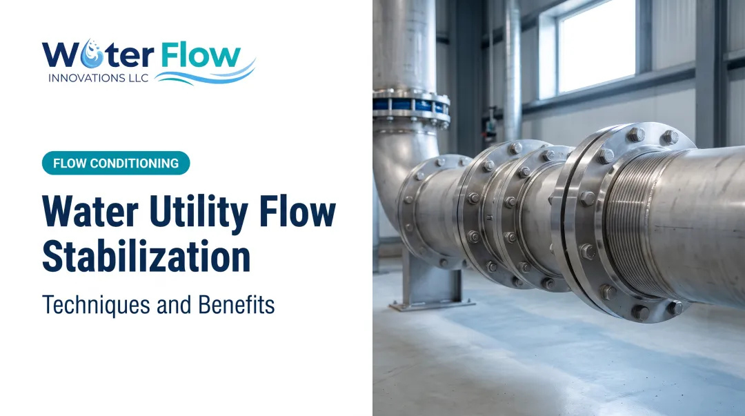
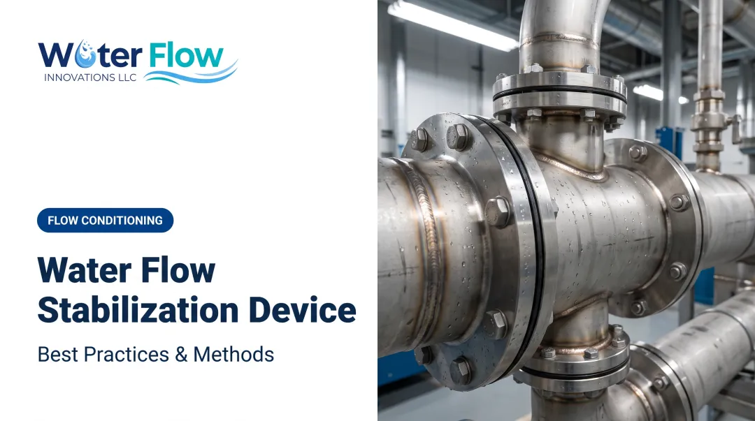
- Flow conditioning technology: tackles turbulence and air entrainment at the source rather than compensating for it downstream.
This is where Water Flow Innovation's Flow Conditioning Device (FCD) fits in. It's a certified system (IAPMO, NSF, ANSI, CAN 61, KIWA, GMP, and SQF) that combines four functions in one unit:
- Air/gas separation: creates a compression zone that promotes laminar flow and keeps bubbles out of the measurement or process zone
- Pressure regulation: reduces water hammer and surge events from pump cycling
- Check valve function: limits reverse flow and pressure spikes that reintroduce air
- Turbulence elimination: slows velocity enough to prevent vortex formation, especially during CIP cycles, tank filling, or irrigation events
The design produces negligible pressure loss, meaning it stabilizes flow without robbing the system of performance.

System Design Corrections
Sometimes the fix is simpler than a new device:
- Correct undersized suction piping
- Minimize elbows near the pump inlet
- Maintain adequate tank submergence levels
These corrections prevent turbulence-driven instability before it ever reaches the impeller, which is cheaper than chasing symptoms downstream.
Cavitation and Its Role in Flow Instability
Cavitation damages pumps and destabilizes flow. Vapor bubbles form when local pressure drops below the liquid's vapor pressure, then collapse violently near internal surfaces. That collapse pits impeller surfaces, disrupts steady discharge, and causes progressive performance loss over time.
Field symptoms include:
- Gravel-like or rattling noise from the pump casing
- Increased vibration
- Fluctuating discharge pressure
- Gradually declining head and efficiency
The underlying issue is usually NPSH margin: Net Positive Suction Head Available (NPSHA) must exceed the manufacturer's required value (NPSHR). When that margin shrinks, cavitation starts and output begins to swing.
Here's the part people miss: replacing a pitted impeller without correcting suction conditions just guarantees a repeat failure. Fix the root cause, not only the symptom:
- Low submergence
- Restrictive suction piping
- Suction lift too aggressive for the liquid's vapor pressure

Monitoring and Maintenance for Long-Term Flow Stability
Consistent monitoring catches instability before it causes damage. Track these core indicators:
- Suction pressure — early warning for entrainment or restriction issues
- Discharge pressure — flags system resistance changes
- Motor current — reveals developing mechanical faults
- Vibration — often the earliest sign of cavitation or wear
Compare real-time readings against your pump's baseline curve data. A gradual drift from that curve tells you something has changed, often before it's visible in output.
Rather than inspecting wear rings, impellers, and strainers on a fixed calendar schedule, tie inspections to operating hours. A pump running 24/7 wears differently than one cycling intermittently, and hour-based scheduling catches issues that calendar-based schedules miss.
What Makes a Water Pump High Flow (and How to Maintain It)
High-flow pumps combine three things:
- A larger impeller diameter
- An optimized volute design that efficiently converts kinetic energy to pressure
- Adequate motor horsepower matched to the system's actual head requirements
Diameter and speed changes follow the affinity laws: flow scales directly, head with the square, and power with the cube. A worked example from Wilo shows increasing impeller diameter from 12 to 14 inches raised flow from 150 to 174 gpm, but power jumped from 10 to nearly 16 hp. Bigger isn't free.

Here's the catch: even a properly rated high-flow pump loses effective output without turbulence control. All the horsepower and impeller sizing in the world won't help if air entrainment or turbulence at the inlet corrupts flow before it reaches the measurement point. That loops right back to the stabilization techniques above.
Frequently Asked Questions
Will cavitation damage a pump?
Yes. Cavitation causes impeller pitting and progressive performance loss as vapor bubbles collapse against internal surfaces. Correcting suction conditions, not just replacing the impeller, prevents it from recurring.
What makes a water pump high flow?
High flow comes from a combination of impeller size, volute design, and matched motor power. Turbulence control at the inlet is essential to preserve that rated flow in real-world operation.
How often should pump flow stability be checked?
Monitor suction pressure, discharge pressure, motor current, and vibration regularly, tied to operating hours rather than a fixed calendar. High-duty pumps need more frequent checks than intermittent ones.
Can a flow conditioning device replace mechanical repairs?
No. Flow conditioning reduces turbulence and air entrainment at the source, but it doesn't fix worn impellers, damaged wear rings, or other mechanical failures.
Why does pump output fluctuate even when the pump seems to run normally?
Hidden causes are common: suction-side air entrainment, a partially closed valve, or a system resistance change from a process modification. The pump itself may be fine while the surrounding system has shifted.
Is throttling a good long-term solution for flow control?
No. Throttling wastes energy by adding artificial resistance rather than matching output to demand. It's better suited for short-term adjustments or testing than continuous flow stabilization.
Does pump-generated air entrainment reach the utility bill?
Yes. Meters register whatever passes through them and cannot separate air from water, so air introduced by pump cycling is counted as delivered volume. Correcting it has produced documented reductions averaging 5–30%, peaking at 46%.
How is that corrected without disturbing the pump set?
A licensed plumber or mechanical contractor fits a custom-built device at the municipal supply connection in about an hour, with a brief water shutoff at the meter connection. Impellers, seals, and control settings are untouched.