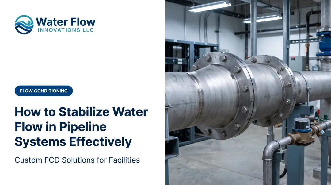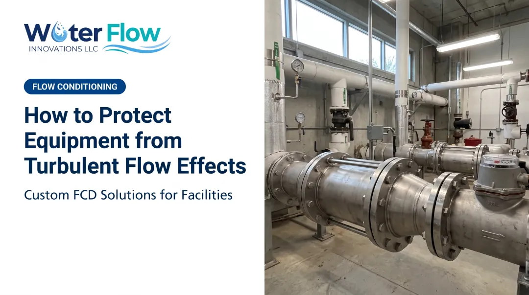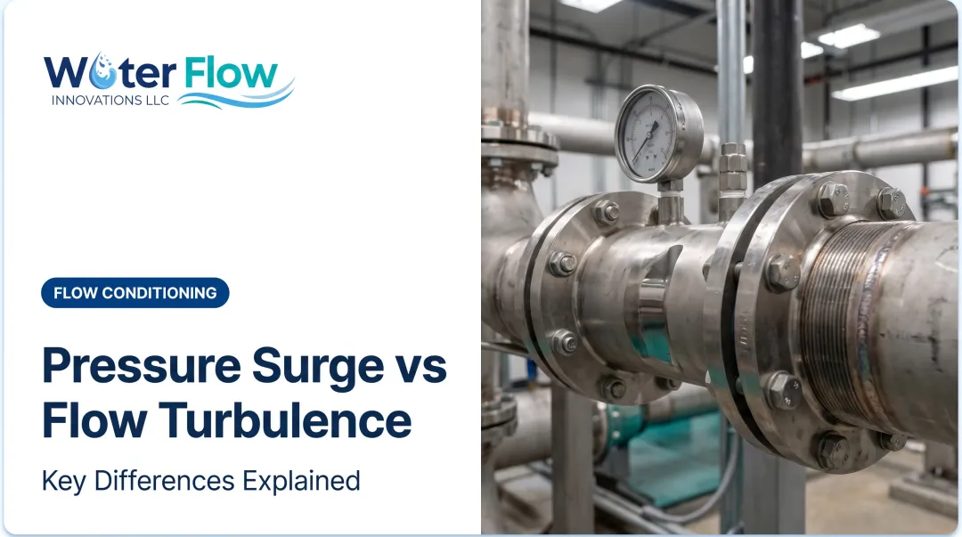

These disturbances are common in piping infrastructure, and they affect system performance more often than most facility managers realize. Rotational and turbulent flow patterns get lumped together and misunderstood, leading to inaccurate metering, wasted energy, and maintenance headaches that seem to appear out of nowhere.
This guide breaks down how rotational flow actually works inside a pipeline, why it matters for your operation, and how it's managed in real-world systems today.
Key Takeaways
- Rotational flow means fluid particles spin on their own axis as they move—vorticity is nonzero
- When vorticity is zero, flow is irrotational: particles translate without spinning
- Bends, valves, pumps, and wall friction all generate rotational flow in real pipelines
- Uncorrected swirl at the meter can skew readings and inflate water and sewer bills
- Flow conditioning devices restore uniform velocity profiles so swirl is reduced at the meter
What Is Rotational Flow?
Rotational flow happens when fluid particles rotate about their own axis as they travel along the pipe. Engineers measure this rotation using vorticity, defined mathematically as the curl of the velocity field. If vorticity is nonzero anywhere in the flow, that flow is rotational.
It is a natural consequence of viscosity, wall friction, and pipe geometry, not a design flaw. Every bend, valve, or fitting disturbs the velocity profile and generates rotation. The no-slip condition at pipe walls is a viscous process that both creates and spreads vorticity through the flow field.
What rotational flow is not:
- Distinct from turbulence (chaotic velocity fluctuations)
- Compatible with smooth-looking flow, which can still carry vorticity
- Present without visible spiraling, through rotational components tied to velocity gradients
Simulations can model the physics, but operators still need to know why swirl forms and how it behaves. That knowledge drives better decisions on meter placement and conditioning equipment.
Rotational flow intensity is not constant. It varies by flow regime: laminar flow behaves differently than turbulent flow, and nearby fitting geometry changes how much swirl develops and how long it lasts downstream.

How Does Rotational Flow Work in a Pipeline?
Rotational flow develops through a sequence of stages as fluid moves through pipeline components. Understanding each stage helps explain why swirl shows up where it does, and why straight pipe alone rarely eliminates it.
Initiation
Rotation typically starts at a geometry change: an elbow, valve, pump discharge, or a run of upstream turbulence entering a straight section. This is condition-based, not something anyone deliberately introduces.
The industry standard API MPMS 5.3 identifies a wide range of triggers, including valves, pumps, strainers, fittings, misaligned joints, protruding gaskets, and weld projections. A common bottleneck: insufficient straight pipe length after a disturbance simply doesn't give the flow time to stabilize at the meter or process point.
Vorticity and Swirl Formation
Think of vorticity as a "spin" measurement: it tracks velocity gradients across the pipe's cross-section. Physically, fluid near the pipe wall moves slower than fluid in the core. That mismatch creates shear layers, which roll up into circulating eddies.
This has real performance consequences:
- Increased turbulence intensity near the disturbance
- Air entrainment, especially during variable-demand cycling
- Localized pressure fluctuations that can persist for many pipe diameters
One published PIV study on a 3D dual-elbow configuration found strong spiral flow that remained significant through an 8-diameter measurement region. Severe cases involving out-of-plane elbows or headers can carry swirl beyond 100 pipe diameters, far past what a "standard" straight run would ever fix.
Regulation and Correction
Flow conditioning systems exist to restore a uniform velocity profile and reduce swirl at the critical measurement point. Straightening vanes and dedicated flow conditioners work by dissipating rotational energy without introducing major pressure loss.
Water Flow Innovation's Flow Conditioning Device (FCD) addresses the problem with a four-component system:
- Air & Gas Separation: creates static back-pressure that promotes laminar flow and a homogeneous water column back through the meter
- Pressure Regulation: controls flow and pressure at the meter entry point, reducing water hammer and surges from on/off cycling
- Check Valve: prevents reverse flow and pressure spikes so air cannot re-enter after purging (select installations)
- Turbulence Elimination: slows velocity at the meter just enough to prevent vortex formation without restricting the water passage

Uncorrected rotational flow at a meter can bias readings, and independent testing confirms it. Research published in Flow Measurement and Instrumentation found that disturbed flow can cause ultrasonic meters to register between -6% and +1% depending on distance from the disturbance.
Turbine meters in NIST testing showed shifts up to 2% near a severe double-elbow fitting. The direction and size of the error depend on meter type, geometry, and distance. The meter is not always over-reading, but it is rarely accurate.
What Corrected Flow Delivers
Properly managed rotational flow produces stable, accurate readings and consistent system pressure. For facilities running the FCD, that stability shows up on the utility bill: documented water and sewer reductions averaging 5-30%, with a highest recorded reduction of 46%.
Installation usually takes about an hour, and roughly 90% of customers reach full ROI within 12 months.

Rotational Flow vs. Irrotational Flow
Irrotational flow is the theoretical counterpart to rotational flow. Vorticity is zero everywhere, and fluid particles translate without spinning. This is the idealized "potential flow" model used in classical fluid dynamics.
| Factor | Rotational Flow | Irrotational Flow |
|---|---|---|
| Vorticity | Nonzero | Zero everywhere |
| Particle motion | Rotates while translating | Translates only |
| Governing math | Navier-Stokes equations | Laplace's equation / Bernoulli |
| Real-world presence | Common in every pipeline | Idealized approximation only |
Real pipelines almost never exhibit purely irrotational flow. Viscosity and wall friction generate vorticity at the boundary.
Potential flow theory is still useful for certain calculations. It cannot represent the no-slip shear layer that exists at every pipe wall.
Where Rotational Flow Is Encountered in Pipeline Systems
Rotational flow shows up most predictably at specific pipeline locations:
- Elbows and tees, especially when stacked close together out of plane
- Partially open valves that create asymmetric flow paths
- Pump discharge sections
- Headers with multiple branch connections
- Areas directly downstream of meters or strainers

Rotational effects intensify under certain conditions:
- High flow velocity
- Tight bend radii
- Insufficient straight-pipe runs between disturbance and measurement point
This matters most in facilities with complex piping and high water-cost sensitivity. Food and beverage plants, municipal water systems, manufacturing sites, hotels, and healthcare campuses all rely on accurate flow measurement to control operating costs.
A hospital with cooling towers, or a food plant running CIP systems, sees constant on/off cycling. That variable demand generates entrained air and unstable flow near the meter.
Conclusion
Rotational flow is a predictable outcome of geometry and fluid viscosity in every pipeline system. Bends, valves, and pumps will always disturb the flow path to some degree.
How you handle that rotational energy at the meter determines whether the system stays efficient or quietly drives up costs. Understanding swirl and vorticity supports better operational choices, including flow conditioning that improves metering accuracy and cuts unnecessary utility spend.
Frequently Asked Questions
What is rotational flow?
Rotational flow occurs when fluid particles spin around their own axis while moving through a pipeline, indicated by nonzero vorticity. It's a natural result of viscosity and wall friction, not a system malfunction.
What is the difference between rotational flow and irrotational flow?
Rotational flow has nonzero vorticity, with particles both spinning and translating. Irrotational flow has zero vorticity everywhere, meaning particles move without rotating — a condition rarely found in real, viscous pipe flow.
What causes rotational flow in pipes?
Bends, valves, pumps, strainers, and general wall friction are the primary causes. Even misaligned pipe joints or protruding gaskets can generate meaningful swirl.
Does rotational flow affect water meter accuracy?
Yes. Swirl and turbulence near a meter can distort readings, sometimes causing over-registration and sometimes under-registration, depending on meter type, geometry, and distance from the disturbance.
How can rotational flow be reduced or corrected in a pipeline?
Flow straighteners and conditioning devices dissipate swirl to restore a uniform velocity profile. Devices like a flow conditioning device (FCD) combine air separation, pressure regulation, and turbulence elimination to stabilize flow at the meter.
Is rotational flow the same as turbulent flow?
No. Rotational flow refers specifically to particle spin, or vorticity, while turbulence describes chaotic velocity fluctuations. They frequently occur together in pipelines, but they're distinct physical concepts.
Would a different meter model be immune to swirl?
No model is immune while the swirl persists, and any meter still registers entrained air as water. Replacing the instrument leaves the vorticity untouched, so the same distortion returns on the next cycle.
What does removing swirl at the meter recover financially?
Documented installations average a 5–30% cut in combined water and sewer charges, with a highest documented single result of 46%, applied from the first billing cycle after installation.