
Here's the problem: a water meter doesn't always measure what you think it measures. Entrained air, pressure swings, and turbulent flow near the meter can all push the reading higher than actual consumption, even when your plant hasn't used an extra gallon.
This article is written for U.S. ethanol plant owners, operations managers, engineers, and sustainability teams trying to sort out water-flow measurement issues from genuine utility costs. Water flow conditioning devices get confused with filtration systems, wastewater treatment, or conservation equipment constantly. They're none of those things. We'll walk through what they actually do, where they might fit in your plant, and how to tell if one is worth investigating.
Key Takeaways
- A flow conditioning device stabilizes water flow before the meter without cutting the volume your process needs.
- Air entrainment, pressure shifts, and turbulence can cause meters to over-register water use.
- Treat water consumption, billing, sewer charges, and process performance as separate questions.
- Confirm any claimed savings with your own meter data and billing history, not spec sheets alone.
What Are Water Flow Conditioning Devices—and Why Are They Used in Ethanol Plants?
A water flow conditioning device is equipment installed in a water line, typically right after the utility meter, to improve the physical condition of the water flowing through that point. The goal is straightforward: give the meter a cleaner, more stable column of water to measure instead of a mix of water, air pockets, and turbulent eddies.
The device does not change how much water your fermentation, cooling, or CIP systems require. It addresses a measurement condition, not a production recipe.
This Is Not a Conservation Measure
Flow conditioning gets lumped in with water-saving equipment more often than it should. It's a different category entirely:
- Cooling tower optimization reduces evaporation and blowdown losses — a real demand reduction.
- Leak repair and closed-loop reuse cut actual withdrawal volumes.
- Low-flow fixtures and CIP-water reduction lower the gallons your process consumes.
- Flow conditioning addresses how accurately a meter registers the water that's already flowing.
Confusing these categories leads to bad expectations. If a plant installs a conditioning device hoping to use less water, it will be disappointed. If it installs one hoping for a more representative meter reading, that's a different and more testable claim.
Why Water Costs Carry Weight in Ethanol Production
Water isn't incidental to ethanol production — it's a major input tracked across several cost lines: purchased process water, cooling and utility water, sewer-discharge fees, and increasingly, sustainability disclosures.
The scale is significant. A June 2019 Argonne National Laboratory survey of mostly dry-mill U.S. ethanol plants, based on 2017 operating data, reports 2.65 gallons of freshwater consumed per gallon of ethanol produced, rising to 2.74 gallons when alternative water sources are included. That same survey found facility-level use averaging 252 million gallons annually, with a median of 178 million gallons.
Those numbers describe actual water demand, not meter accuracy. When bills and ESG figures rest on meter data at that scale, the conditions upstream of the meter start to matter.

When Flow Conditioning Shows Up in Plant Conditions
In ethanol facilities, flow conditioning is usually evaluated under conditions like these:
- High-flow utility lines feeding cooling towers or process water
- Lines with variable or intermittent demand
- Piping systems with long runs, multiple bends, or irregular layouts upstream of the meter
- Installations where air entry or turbulence is suspected but unconfirmed
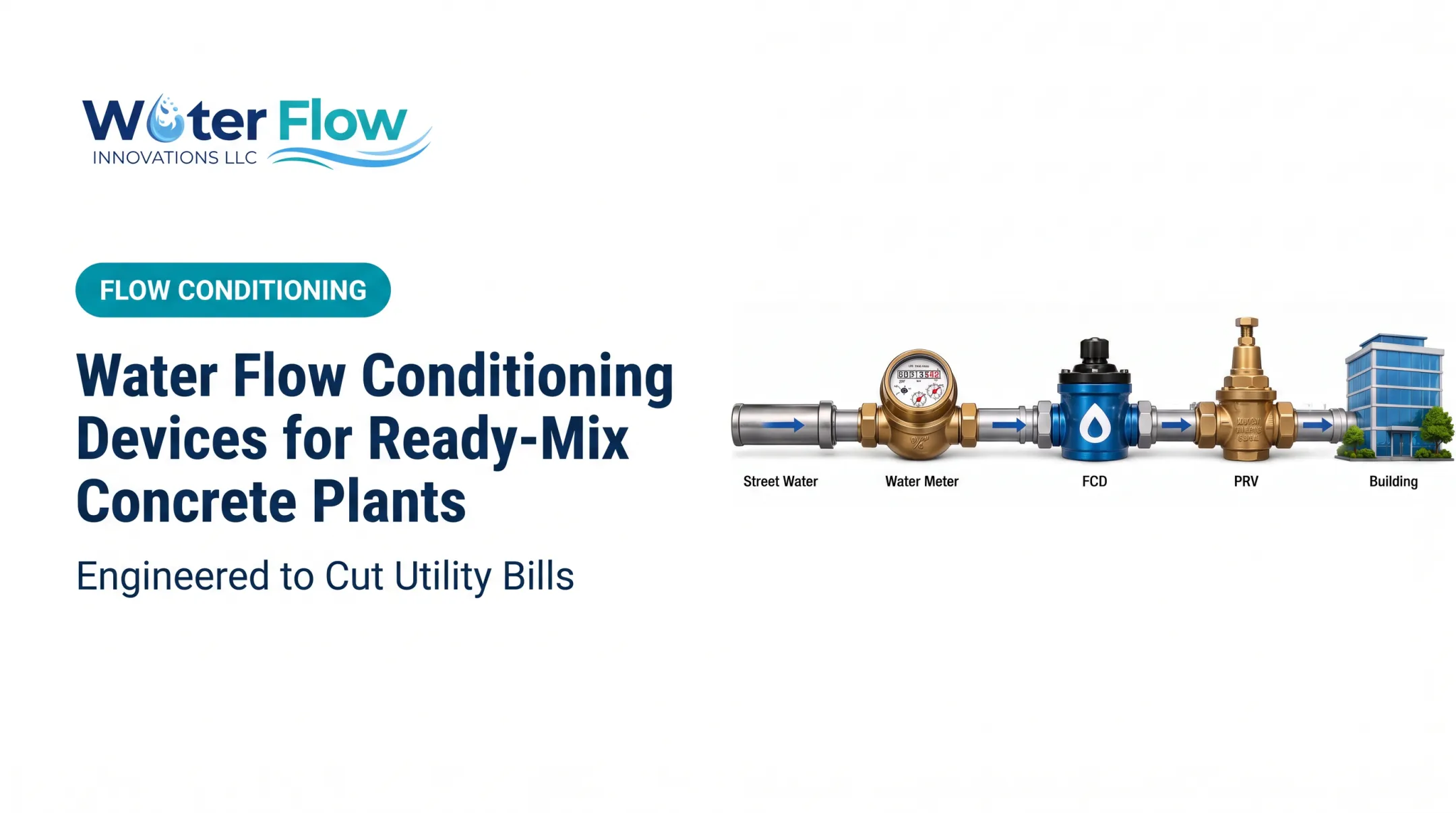
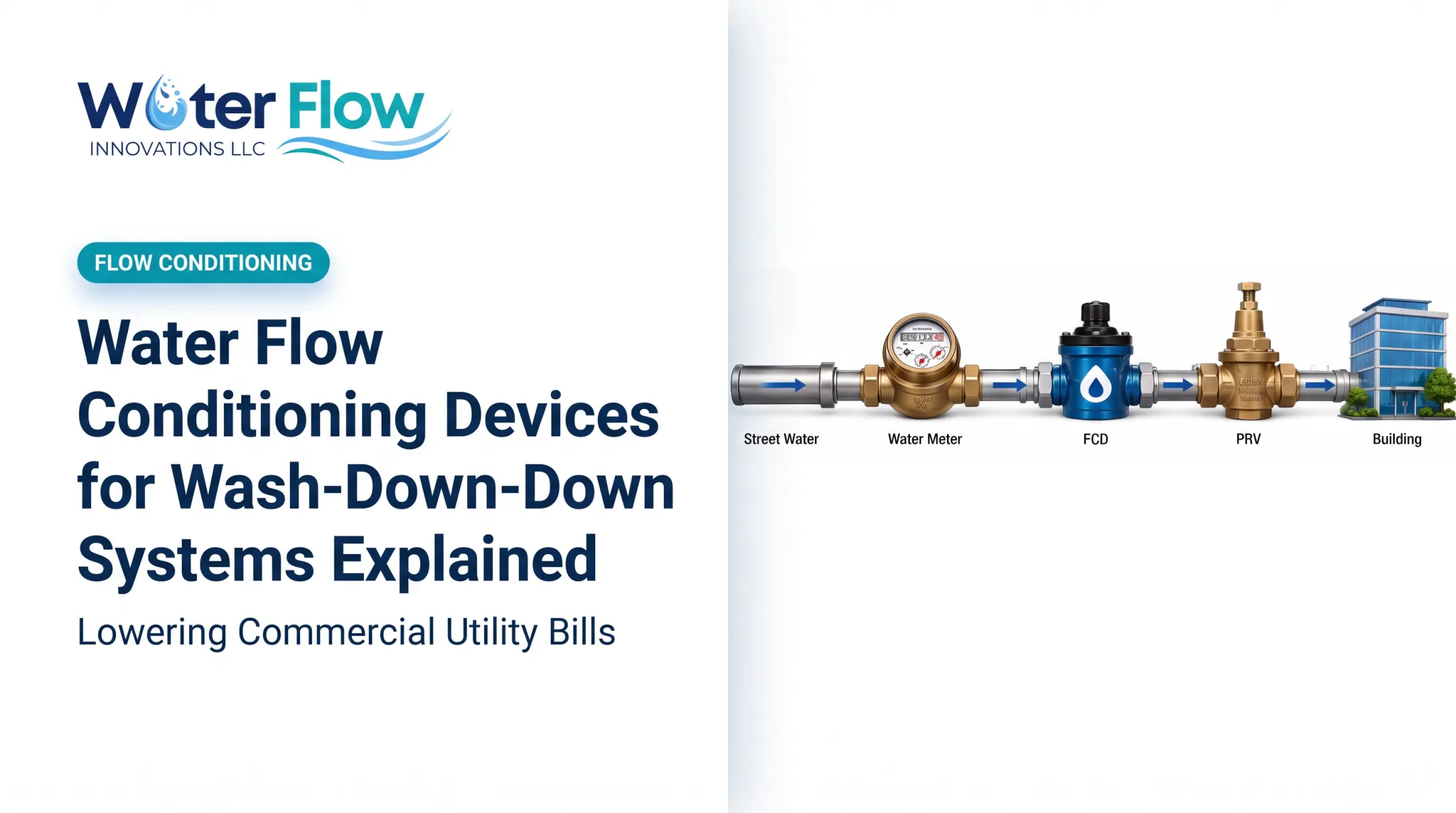
Water Flow Innovation builds its Flow Conditioning Device (FCD) around four components: air and gas separation, pressure regulation, a check valve, and turbulence reduction. The device carries IAPMO, NSF, ANSI, CAN 61, KIWA, GMP, and SQF certifications. Treat any published performance figures as site-specific—confirm them against your own meter data and operating conditions before relying on them as guaranteed outcomes.
How Do Water Flow Conditioning Devices Work?
The basic sequence runs from your incoming utility line, through the conditioning device, to the meter, then downstream to plant operations. Conditions immediately upstream of the meter matter: mechanical and turbine meters register velocity and volume, and both air and turbulence distort what the meter records.
Step 1: Identify and Manage Air or Gas in the Line
Air gets into water lines more often than most operators assume: municipal main repairs, pump cavitation, vacuum formation during service interruptions, and temperature shifts can all introduce air or gas pockets.
A 2023 peer-reviewed laboratory study tested mechanical water meters, including multi-jet and rotary-piston designs, and documented over-registration when air passed through the meter during pipe refilling after intermittent supply.
That finding covers free air in the line, not dissolved air, which behaves differently and does not necessarily produce the same effect. Confirm how your installed model responds in the meter manufacturer's documentation.
Step 2: Stabilize Pressure and Protect Flow Direction
Pressure regulation and check-valve components reduce abrupt pressure changes, water hammer from on-off cycling, and backflow through the meter. Variable demand—a CIP cycle starting, a pump kicking on—can create exactly this kind of instability.
Check the selected meter manufacturer's installation guidance before assuming a given pressure-regulation approach applies to your system. Not every installation needs a check valve; some plants already have adequate backflow protection elsewhere in the line.
Step 3: Reduce Turbulence Before Measurement
Elbows, partly open valves, pumps, reducers, and tees all distort the velocity profile of water moving through a pipe. OIML's international metering standard (R 49-1:2024) acknowledges this by defining multiple upstream and downstream sensitivity classes for meters, rather than one universal rule. The straight-pipe requirement for your specific meter model is the one that counts, not a generic rule of thumb.
A conditioning device is positioned to smooth that velocity profile ahead of the meter. Done correctly, it shouldn't meaningfully restrict flow.

What a conditioning device does not do:
- Remove dissolved contaminants or treat water quality
- Process or treat wastewater
- Increase ethanol yield
- Eliminate leaks anywhere else in the system
- Guarantee lower bills when the meter is already accurate and another factor is driving the charge
Checks After Installation
Before calling an installation complete, verify:
- Pressure drop across the device stays within acceptable limits for your process
- Flow capacity matches your plant's peak demand, not just average flow
- Compatibility with your specific meter model and pipe material
- Access for inspection and maintenance
- Drainage provisions if the device requires them
- Production performance is unaffected after installation — confirm with operations, not just paperwork
Water Flow Innovation designs its device for negligible pressure loss across pipe sizes and meter types. Rare cases have recorded a small psi drop at the meter—treat that as a starting point for your own engineering review, not a final answer for your configuration.
Where Are Water Flow Conditioning Devices Applied, and What Affects Performance?
Mapping Plant Water-Use Areas
Before picking an installation point, review every area where water enters or moves through your plant:
- Cooling systems and cooling tower makeup
- Boiler and steam-support systems
- Fermentation, mash, and distillation support water
- Clean-in-place (CIP) systems
- Fire protection or utility water lines
- Laboratory use and general washdown
Fire protection lines deserve a specific note: flow conditioning devices generally aren't installed on fire service mains, given the safety-critical flow requirements those systems must meet under standards like NFPA 24. Exclude fire service mains entirely; they are not candidates for installation.
What Determines the Right Location
Placement depends on a handful of factors working together:
| Factor | Why It Matters |
|---|---|
| Billing meter location | Device must sit relative to the metered point, not just anywhere in the line |
| Suspected disturbance source | Air entry, turbulence, or pressure swings each point to different fixes |
| Pipe arrangement | Bends, pumps, and fittings upstream affect flow profile |
| Separate supply/sewer billing | Changes what's actually being measured and charged |
Meter type and size, pipe diameter, pump operation, pressure range, and demand variability all factor into whether a given location will perform as expected.
Investigate Before You Install
A credible evaluation starts with data, not assumptions:
- Pull bills and interval meter data for several billing cycles
- Compare billed volume to process records (production logs, batch counts, cooling makeup)
- Inspect for leaks and open valves that could inflate readings
- Review piping drawings for upstream disturbances
- Document pressure and flow at the suspected location
- Check air-entry points from main repairs, pump work, or service interruptions
Research applicable codes before any line modification:
- ASME B31.3 for process piping design and testing
- ASME B31.1 or the ASME Boiler and Pressure Vessel Code for power piping or boiler work
- Local plumbing codes and utility rules, confirmed with qualified plant personnel
Measuring Results Without Fooling Yourself
Track these before and after installation, over a controlled period with consistent production conditions:
- Metered volume and production-normalized water intensity
- Sewer-billed volume (often calculated from the same meter)
- Pressure and flow readings at the installation point
- Process-quality indicators, confirming nothing changed downstream
One billing cycle proves little. Rates, seasonal production, and maintenance events can move utility totals on their own, so build a baseline across multiple cycles under comparable production conditions.
Common Issues, Misconceptions, and When a Device May Not Be Appropriate
The Biggest Misconception
A flow conditioning device does not make your plant use less water. It can improve how accurately that water is measured and billed. Genuine conservation requires process, equipment, or maintenance changes — not a device at the meter.
Other Explanations for a High Water Bill
Before assuming meter over-registration is the culprit, rule out these common causes:
- Leaking pipes, valves, or fittings
- Faulty or stuck-open valves
- Excessive cooling-tower losses from evaporation, blowdown, or drift
- Overly frequent or extended CIP cycles
- Recent process changes increasing actual demand
- Sewer-rate changes unrelated to volume
- An incorrectly sized or malfunctioning meter
EPA's cooling tower guidance identifies evaporation, blowdown, drift, and leaks as the standard water exits from a recirculating cooling system. A properly operated tower shouldn't have leaks or overflows at all. If your makeup water is climbing, investigate that before looking at the meter.
When a Device May Not Be the Right Call
Some situations call for a different approach entirely:
- The meter is already properly sized, installed, and verified accurate
- The flow disturbance traces back to a larger piping-design defect needing structural correction
- Required flow capacity exceeds what the device can support
- Pressure loss would be unacceptable for the process
- The line is safety-critical and requires formal engineering sign-off before any modification
Verifying Vendor Claims
Water Flow Innovation offers a 6-month money-back guarantee, a lifetime transferable warranty, and an installation window of roughly one hour for straightforward setups (industrial configurations may run longer). Confirm these terms against the actual contract for your plant. Certifications and warranties describe the product, not a guaranteed dollar outcome at your specific site.

Conclusion
Water flow conditioning devices address one specific thing: the condition under which a meter measures flow, particularly where air entrainment or turbulence may be pushing registration higher than actual use. They aren't conservation equipment, and they won't lower the gallons your fermentation or cooling systems genuinely require.
Separate those two questions from the start. Confirm whether over-registration is actually occurring using your own meter data, piping layout, pressure readings, and billing history — not equipment specifications alone.
From there, the right path depends on site-specific engineering review, meter compatibility, safe installation, and results you can verify in writing, not just assume.
Frequently Asked Questions
How much water does an ethanol plant use?
Water use varies by feedstock, plant design, and cooling strategy. A 2019 Argonne survey of mostly dry-mill U.S. plants found 2.65 gallons of freshwater per gallon of ethanol produced, with facility totals averaging 252 million gallons annually.
What does a water flow conditioning device do?
It conditions air, pressure, flow direction, and turbulence near a water meter to support more representative measurement. It is not a water-treatment or water-conservation device.
Can a flow conditioning device reduce an ethanol plant's actual water consumption?
No. It may reduce billed volume if meter over-registration was occurring, but actual consumption only drops through process efficiency, leak repair, cooling-system optimization, or water reuse.
Where should a flow conditioning device be installed in an ethanol plant?
Placement depends on the billing meter's location, piping configuration, suspected flow disturbances, and the meter manufacturer's requirements. Consult the manufacturer and qualified plant engineering staff before installation.
How can an ethanol plant tell whether a flow conditioning device is working?
Compare baseline bills, interval meter data, pressure and flow readings, and production-normalized water use before and after installation, over a consistent operating period.
Are water flow conditioning devices suitable for every ethanol plant?
Suitability depends on meter type, pipe size, flow conditions, pressure requirements, installation access, and whether over-registration has actually been demonstrated at that site.