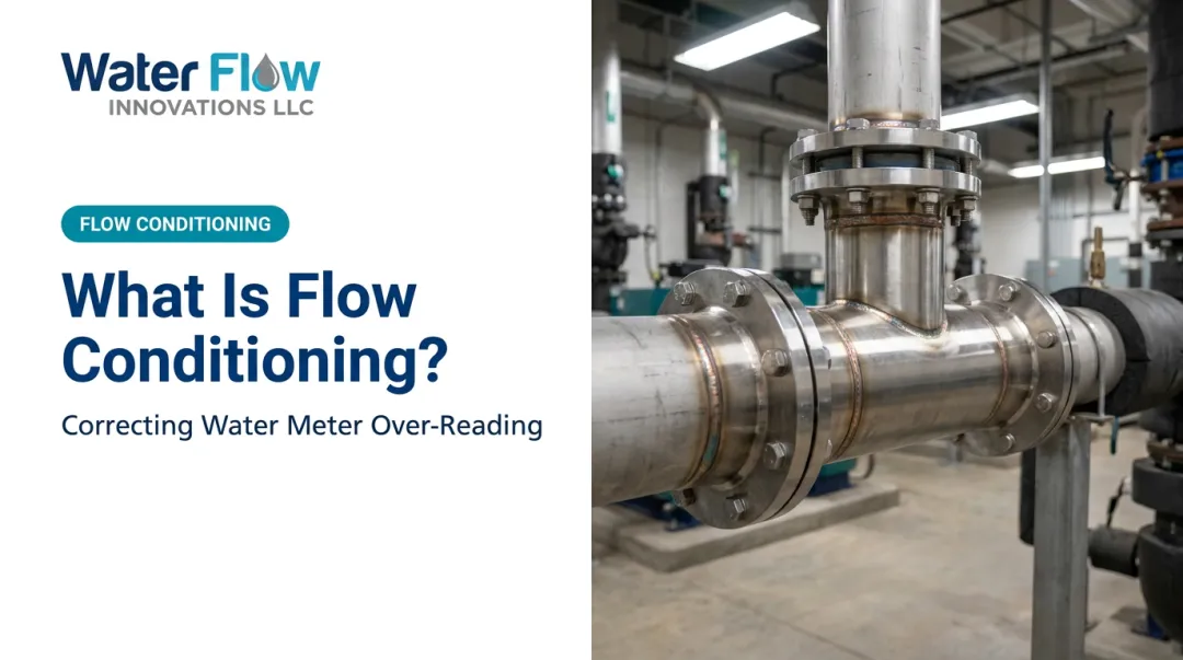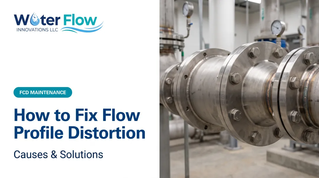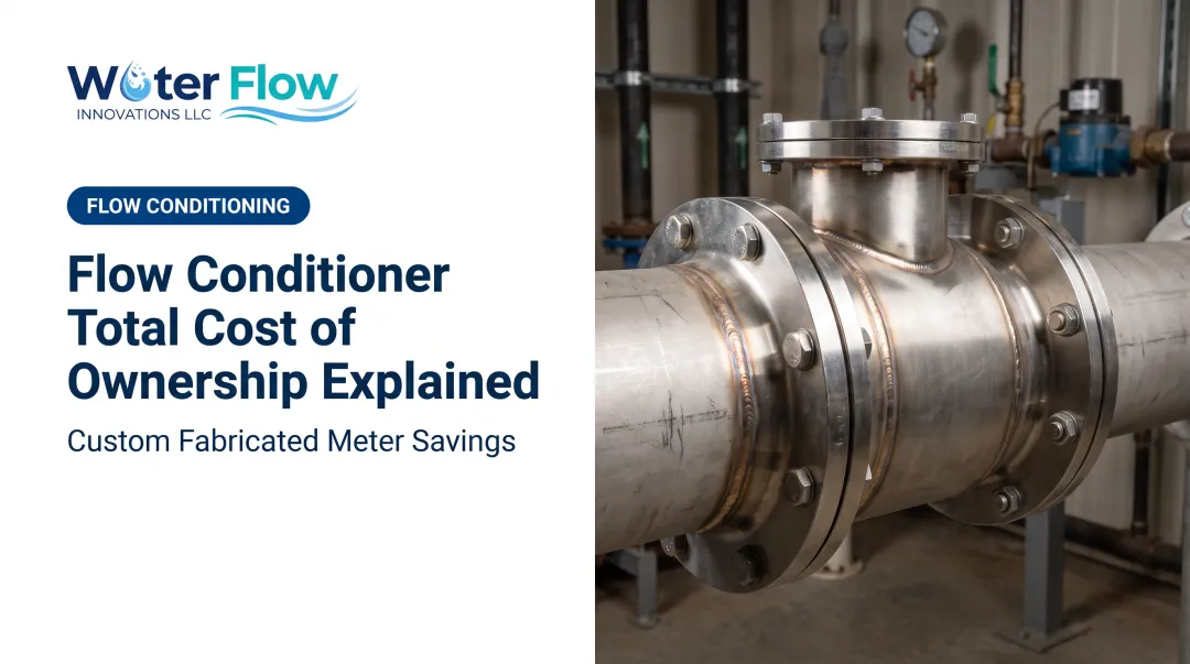

Every elbow, valve, and pump a fluid passes through generates swirl and turbulent kinetic energy that distorts the velocity profile for dozens of pipe diameters downstream. Standards bodies like ISO address this with detailed installation tables specifying required straight-run distances, which vary by meter type, fitting configuration, and beta ratio.
The problem: these devices are everywhere but poorly understood, leading facility managers to misdiagnose meter inaccuracy, chase phantom leaks, or over-engineer piping runs. This guide breaks down what turbulent kinetic energy (TKE) flow conditioners actually are, how they physically work, and where they matter most for measurement accuracy.
Key Takeaways
- TKE flow conditioners remove swirl and non-uniform velocity profiles from upstream fittings
- They break large turbulent structures into smaller ones that dissipate faster through viscosity
- Common types—tube-bundle, perforated/Zanker plate, and Etoile—differ in swirl removal and straight-run needs
- Properly conditioned flow supports accurate metering and reliable billing data
- Water Flow Innovation's FCD applies similar principles to correct meter over-reading from air entrainment and turbulence
What Is a Turbulent Kinetic Energy Flow Conditioner?
A TKE flow conditioner is a device installed in a pipeline to reduce swirl, asymmetry, and turbulent kinetic energy at the meter or process component.
The problem it solves: Fittings such as elbows, valves, and pumps create secondary and helical flows. These distortions can persist for dozens of pipe diameters, throwing off any meter that assumes a symmetric, fully developed profile.
What it is not:
- Not a filter or strainer: it doesn't remove debris
- Not a pressure regulator: pressure control isn't its function
Its sole job is velocity-profile correction.
Even with ultrasonic and electromagnetic meters on the market, conditioners remain relevant. Smart meters still need a reasonably uniform, swirl-free profile to hit their rated accuracy. Better sensors don't eliminate the physics problem upstream.
Common Conditioner Geometries
| Type | Design | Notes |
|---|---|---|
| Tube bundle | Typically 19 parallel tubes, roughly 2-3 pipe diameters long | Suppresses rotation, produces strong outlet jets |
| Perforated/Zanker plate | Many small holes redistribute momentum | Addresses both swirl and asymmetry |
| Etoile (star) | Radial axial vanes | Different recovery behavior at different Reynolds numbers |

Swirl removal performance and required development length differ significantly by geometry. A tube bundle and an Etoile straightener aren't interchangeable solutions for the same disturbance.
How Does a TKE Flow Conditioner Work?
Conditioners operate through a sequence: disturbance interception, turbulence breakdown, then flow recovery. There are no moving parts. The process is purely geometric.
Initiation
Disturbed, swirling flow generated by upstream bends, pumps, or valves enters the conditioner passively. Since there's nothing mechanical to activate, performance is entirely dependent on upstream geometry and installation.
Common bottlenecks:
- Insufficient spacing between the disturbance source and the conditioner inlet
- Undersized conditioners relative to the pipe's Reynolds number range
- Misaligned installation that undermines the intended flow path through the conditioner
Core Operation
As flow passes through small tubes, holes, or vanes, large-scale swirling eddies get physically broken into many smaller-scale eddies. This is the central mechanism.
Computational fluid dynamics research on 19-tube bundles, using SST RANS modeling (k-omega near walls, k-epsilon in the free stream), shows strong jets exiting each tube. Those jets raise turbulent kinetic energy near the outlet, then it decays rapidly downstream. Conditioning redistributes turbulence and allows recovery; it does not wipe turbulence out on contact.
Smaller eddies dissipate energy through viscosity far faster than the original large-scale secondary flow. The design trades one stubborn disturbance for many small ones that die off quickly.

Regulation of Swirl and Turbulence
Conditioner geometry (tube length, plate thickness, hole pattern) governs how fast swirl intensity and velocity distortion decay downstream.
Peer-reviewed CFD studies on 19-tube bundles found swirl intensity decaying exponentially downstream of the conditioner in the tested configuration, though performance isn't fully independent of Reynolds number. Higher Reynolds numbers can demand longer development lengths.
Here's the counterintuitive finding: longer isn't always better. Multiple studies found that increasing conditioner tube length produced only slight additional swirl reduction, with little change in downstream recovery. Standard, shorter designs are often the more cost-effective choice.
Output and Recovery of Fully Developed Flow
The end goal is a uniform, axisymmetric, swirl-free velocity profile matching naturally developed straight-pipe flow. This corrected profile is what allows orifice plates, ultrasonic meters, and magnetic meters to read within their rated tolerances.
One peer-reviewed ASME experiment on a cone-swirl conditioner recorded metering error dropping from roughly 1.5% with a swirl disturbance to about 0.5% with conditioning. Those figures are apparatus-specific, but they show the real-world stakes of getting this right.
Where TKE Flow Conditioners Are Used
TKE flow conditioners are typically fitted in the straight run serving a flow meter: after bends, pumps, valves, or expanders/reducers, and serving custody-transfer or process metering points.
They perform best in these conditions:
- Pipelines with limited straight-run space available
- High-value fluid transfer (oil, gas, water, or chemicals)
- Facilities requiring billing-grade measurement accuracy
Standards and hardware still vary by industry. Oil and gas custody transfer follows API MPMS Chapter 14.3 and AGA Report No. 3 for orifice-meter installation.
Water and wastewater utilities, food and beverage plants, and large commercial systems use the same turbulence-reduction idea. Device types and governing standards differ by sector and application.
Why Uncorrected Turbulence Costs You Money
Turbulent, swirling flow at a water meter commonly causes meters to over-read actual consumption. Standard displacement and turbine meters are calibrated for straight, developed flow. They can't tell entrained air and micro-bubbles from real water moving through the line.
That over-reading translates directly into inflated water and sewer bills, since utilities bill based on metered volume, not real usage.
That bill impact is what Water Flow Innovation built the Flow Conditioning Device (FCD) to stop. The FCD is certified to IAPMO, NSF, ANSI, CAN 61, KIWA, GMP, and SQF standards and uses a four-component system:
- Air and gas separation: removes entrained air and micro-bubbles at the meter
- Pressure regulation: manages excess supply pressure
- Check valve: prevents backflow-related turbulence
- Turbulence elimination: corrects the velocity profile itself
Each unit is custom-fabricated in 316L stainless steel for 1/2 inch to 12 inch pipe (options through 20 inches / DN20–DN500). It works with any meter type, so you do not need a meter swap.

Documented customer results include:
- 5–30% typical reduction in combined water and sewer costs
- 46% highest documented single-site savings
- Savings on the next billing cycle, with install usually about an hour and no operational disruption

Conclusion
TKE flow conditioners work by physically breaking large turbulent structures into smaller ones that dissipate faster through viscosity. That restores a uniform flow profile the meter can actually trust. Understanding this mechanism changes how facility managers approach specification, installation, and maintenance.
Correctly conditioned flow protects equipment and improves metering accuracy. With Water Flow Innovation's FCD, that accuracy can translate into real, verifiable utility savings starting with your very next bill.
Frequently Asked Questions
What does turbulent kinetic energy mean?
TKE is the average kinetic energy contained in the velocity fluctuations of turbulent flow, calculated from the variance of the fluctuating velocity components. It's the standard metric engineers use to quantify turbulence intensity.
Can you use Bernoulli's equation for turbulent flow?
Bernoulli's equation strictly applies to inviscid, steady flow along a streamline. Engineers commonly apply modified, practical versions to turbulent flow by adding head-loss terms that account for friction and turbulence.
How long does flow need to travel after a bend before it's "developed"?
Required straight-run distance varies by standard, meter type, and fitting configuration. There's no single universal number. A properly designed flow conditioner can shorten the needed distance to just a few pipe diameters.
Do flow conditioners cause pressure loss?
Most conditioners introduce some pressure drop from the physical obstruction, though designs vary widely. Water Flow Innovation's FCD is engineered for negligible pressure loss, with no meaningful impact on system performance.
Can a flow conditioner fix an inaccurate water meter reading?
Yes, if the inaccuracy comes from turbulence-induced over-reading rather than a broken meter. A certified flow conditioning device can correct the distorted profile and reduce billed volume without replacing the meter.
What's the difference between a flow conditioner and a flow straightener?
The terms are often used interchangeably, but a straightener typically removes swirl with little effect on an asymmetric velocity profile. A conditioner is generally built to address both swirl and asymmetry together.
How is turbulence intensity translated into a savings estimate?
Through a free review of your water and sewer bills alongside meter size, pipe size, line pressure, and PRV configuration. Those inputs, rather than a CFD model, establish the projected range and the device sizing.
Can the same approach be applied across an engineering group's sites?
Yes. Each site with its own metered municipal connection is a separate installation opportunity, so results compound and before-and-after billing evidence aggregates for corporate benchmarking and capital planning.